


4-21
Cisco ASA 5585-X Adaptive Security Appliance Hardware Installation Guide
OL-22567-02
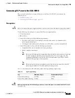
Chapter 4 Maintenance and Upgrade Procedures
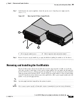
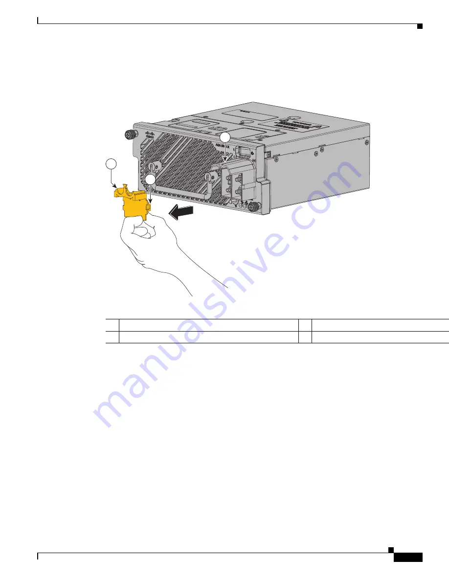
Removing and Installing the Power Supply Module
Step 3
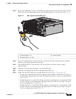
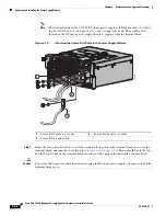
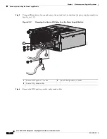
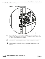
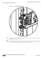
Remove the terminal block cover by simultaneously squeezing the left and right sides of the terminal
block, and at the same time pulling the cover off the terminal block; set the cover aside (
Figure 4-17
).
Figure 4-17
Removing the Terminal Block Cover
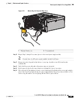
Step 4
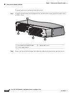
Using a 5/16-inch nut-driver, loosen and remove the four nut and lock-washer pairs on the terminal
block posts. Set the nuts and lock-washers aside.
Step 5
Using an M4 nut-driver, loosen and remove the nut and lock-washer from the power supply
ground terminal.
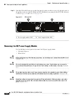
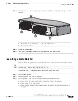
Step 6
Attach the source DC power cable lugs to the source DC cables.
Step 7
Attach the source DC ground wire lug to the source DC ground wire.
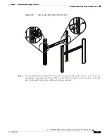
Step 8
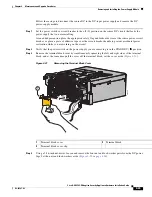
Connect the source DC cables to the terminal block in this order (
Figure 4-18 on page 4-22
):
•
Position the ground cable lug on the power supply ground terminal post. Slide the lock-washer over
the ground post and tighten the nut to secure the source DC ground wire. Do not over-tighten the nut
(see
Table 4-5
).
•
Position the negative (–) source DC cable lug on the power-supply negative (–) terminal posts. Slide
the lock-washers over the terminal posts and tighten the nuts to secure the source lug to the posts.
Do not over-tighten the nuts (see
Table 4-5
).
•
Position the positive (+) source DC cable lug on the power supply positive (+) terminal posts. Slide
the lock-washers over the terminal posts and tighten the nuts to secure the source lug to the posts.
Do not over-tighten the nuts (see
Table 4-5
).
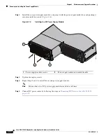
1
Terminal block cover
2
Terminal block
3
Terminal block cover clip
1150W DC
2
3
1
33
452
8


