2-6
Cisco Aironet 350 Series Bridge Hardware Installation Guide
OL-1412-01
Chapter 2 Installation
Connecting the Antenna Cable
Connecting the Antenna Cable
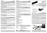
The bridge provides two reverse TNC antenna connectors on the rear of the unit (see
Figure 2-1
) for
diversity configurations with two antennas. When you are using a single antenna, you should connect
the antenna to the Right/Primary connector.
Figure 2-1
Connecting the Ethernet Cables
Follow these steps to connect the straight-through Category 5 Ethernet cable and power supply to the
bridge:
Step 1
Plug the RJ-45 Ethernet connector into the Ethernet port on the back of the bridge.
Step 2
Choose a power option for the bridge. The 350 series bridge receives power through the Ethernet
cable.The 350 series bridge power options include:
•
A switch with inline power, such as a Cisco Catalyst 3524-PWR-XL
•
An inline power patch panel, such as a Cisco Catalyst Inline Power Patch Panel
•
A Cisco Aironet power injector
CIS
CO AIR
ONE
T 350
S
ER
IES
WI
RE
LE
SS
A
CC
ES
S
PO
IN
T
ET
HE
RN
ET
A
CT
IV
IT
Y
AS
SO
CIA
TIO
N S
T AT
US
RA
DIO
A
CT
IV
IT
Y
SERIAL POR
T
ONLINE PO
WER ETHERNET
LEFT
RIGHT/PRIM
ARY
Antenna
connectors
Right/Primary


