SERVICE MANUAL
Transmig 165
ST
Transmig 165
ST
SERVICE MANUAL
Transmig 165
ST
Transmig 165
ST
Manual 0-5442
10-1 TROUBLESHOOTING
10.01 Basic Troubleshooting-Power Source Faults
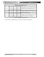
The following table is a guide for analysing problems and making repairs to the Power Source.
Fault
Possible Cause
Remedy
1 There is no weld
output and all front
panel displays are off
A
B
C
D
E
F
G
The main Power Switch is set to OFF
Line fuse is blown
The main Power Switch is faulty
Loose connection to EMC board
Faulty Power Inverter board
Faulty Control board
Faulty Front Panel Control PCB
A
B
C
D
E
F
G
Set main Power Switch to ON
Replace Line fuse
Replace main Power Switch
Tighten connections
Replace Power Inverter board
Replace Control board
Replace Front Panel Control
PCB
2 There is no weld
output and all front
panel displays are off
or flickering on & off
A The internal protection circuit to shut
the unit down if the mains supply
voltage is too high has operated
A
Check to see if mains supply
voltage is <274VAC. A
generator with poor voltage
regulation may cause a supply
voltage in excess of 274VAC.
Connect Power Source to a
supply voltage <274VAC.
3 There is no weld
output and the yellow
over temperature light
is on
A
B
C
Unit has overheated
Airflow inlet or outlet ducts are
blocked
Fan does not operate
A
B
C
Allow unit to cool, refer
4.02.15, with fan on until over
temperature light extinguishes
Remove blockages from
airflow ducts
Replace fan. Check fan wiring
header is plugged securely
into Control board. Check fan
wiring is not damaged
4 Mode switch does not
change welding mode
A Faulty Front Panel Control PCB
A
Replace Front Panel Control
PCB
5 The wirefeed motor
and the weld output
do not operate when
the torch trigger
switch is depressed
A
B
C
D
E
F
G
Internal wiring fault
Over temperature light is on
Trigger wires shorted to weld voltage
inside torch
Trigger wires or torch switch faulty
Faulty Power Inverter board
Faulty Control board
Faulty Front Panel Control PCB
A
B
C
D
E
F
G
Check continuity of internal
wiring from Torch adaptor
through to boards
Allow unit to cool, refer
4.02.15, with fan on
Repair trigger wires in torch
Check & Repair
Replace Power Inverter board
Replace Control board
Replace Front Panel Control
PCB
6 The wirefeed motor
does not operate
when the torch trigger
switch is depressed
A
B
C
D
Power Source set to TIG or STICK
mode
Wirefeeder motor wiring has become
loose
Trigger wires or torch switch faulty
Faulty Power Inverter board
A
B
C
D
Set power Source to MIG mode
Check motor wiring
Check & Repair
Replace Power Inverter board
7 The wirefeed motor
operates at maximum
speed and cannot be
adjusted.
A
B
Faulty Power Inverter board
Faulty Front Panel Control PCB
A
B
Replace Power Inverter board
Replace Front Panel Control
PCB
Table 10-1 Power Source Faults
SECTION 10:
TROUBLESHOOTING
Содержание Transmig 165ST
Страница 16: ...SERVICE MANUAL Transmig 165ST Transmig 165ST GENERAL INFORMATION 1 10 Manual 0 5442 Notes ...
Страница 32: ...OPERATION 4 6 Manual 0 5442 SERVICE MANUAL Transmig 165ST Transmig 165ST Notes ...
Страница 84: ...SERVICE MANUAL Transmig 165ST Transmig 165ST THEORY OF OPERATION 9 2 Manual 0 5442 Notes ...
Страница 115: ...SERVICE MANUAL Transmig 165ST Transmig 165ST Manual 0 5442 12 3 ASSEMBLY PROCEDURE 8 7 A 10011 9 A 10012 ...
Страница 118: ...SERVICE MANUAL Transmig 165ST Transmig 165ST ASSEMBLY PROCEDURE 12 6 Manual 0 5442 14 Art A 13011 ...
Страница 120: ...SERVICE MANUAL Transmig 165ST Transmig 165ST ASSEMBLY PROCEDURE 12 8 Manual 0 5442 Notes ...
Страница 125: ...SERVICE MANUAL Transmig 165ST Transmig 165ST This Page Intentionally Blank ...

