23
Communication
Un pupitre de commande et d’affichage
Le pupitre de commande et d’affichage sera intégré en stan-
dard et visible de l’extérieur par une fenêtre sur la porte de l’ar-
moire électrique.
Le pupitre permettra les fonctions suivantes :
– Marche / arrêt,
– Sélection chaud / froid,
– Test-lampes,
– Modifications des consignes et des paramètres,
– Affichage des températures,
– Visualisation par leds de tous les états de :
Fonctionnement :
Compresseur,
Chaud-froid.
Défaut :
Moteurs compresseurs, ventilateurs extérieurs,
Haute et basse pression,
Antigel,
Débit eau.
Le MRS3, met à disposition pour la synthèse défaut, un contact
libre de tout potentiel (fermeture ou ouverture).
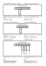
Bornes disponibles pour les commandes externes :
– Marche / arrêt,
– Sélection chaud / froid.
– Sélection consigne 2.
Commande électronique à distance
(option)
qui permettra les fonctions suivantes :
– Marche / arrêt avec signalisation,
– Test lampes,
– Modifications des consignes,
– Sélection consigne 2,
– Affichage de la température ou de la consigne,
– Sélection chaud / froid,
– Signalisation par leds du froid, du chaud, des étages en fonc-
tionnement,
– Défaut de synthèse.
Carte de relayage (option)
Cette carte permettra de reporter à distance tous les états de
défauts et de fonctionnement en mettant à disposition des con-
tacts sans potentiel. Elle sera reliée au groupe par une paire de
fils torsadés avec écran type téléphonique, la longueur pouvant
atteindre 3000 m.
Description des cartes et raccordements voir manuel MRS3-4.
Communication
A control and display panel
The control and display panel will be integrated as standard and
visible from the exterior by means of a window on the electrical
cabinet door.
The panel allows the following functions :
– Start / stop,
– Hot / cold selection,
– Lamp test,
– Set point and parameter modification,
– display of temperatures,
– LED visualization of all unit statuses for :
Operation :
Compressor,
Hot / cold.
Fault :
Compressor motors, external fans,
High and low pressure,
Antifreeze,
Water flow rate.
The MRS 3 provides a potential free contact for fault synthesis
(closed or open).
Terminals for external controls :
– Start / stop,
– Heating / cooling selection.
– Set point 2 selection.
Electronic remote control (optional)
which allows the following functions:
– Start / stop with display,
– Lamp test,
– Set point modifications,
– Set point 2 selection,
– Temperature or set point display,
– Heating / cooling selection,
– LED display for cooling, heating, and stages in operation,
– Fault synthesis.
Relay card (optional)
This card will allow data transfer of all operation statuses and
fault warnings by using potential free contacts. It will be con-
nected to the unit by a pair of shielded telephone type twisted
wires, the length of which can reach 3000m.
Description of cards and connectio, see technical brochure
MRS3-4.

