


Installation proposal
Installation proposal
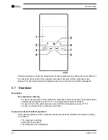
Ref.
Action
1
Main power switch for the compressor (three-phase).
Power supply cables need to be protected by suitable conduit.
2
Main power switch for the dryer (single-phase).
Power supply cables need to be protected by suitable conduit.
3
Install the compressor on a solid, level floor suitable for taking its weight.
The recommended minimum distance between the top of the unit and the ceiling is 2 m (78.7 in).
The air receiver must not be bolted to the floor.
For tank-mounted units, the minimum distance between the wall and the back of the compressor
is 1.5 m (59 in).
4
Position of the dryer.
The pressure drop over the air delivery pipe can be calculated as follows:
Δp = (L x 450 x Q
c
1.85
) / (d
5
x P), with
d = Inner diameter of the pipe in mm
Δp = Pressure drop in bar (recommended maximum: 0.1 bar (1.5 psi))
L = Length of the pipe in m
P = Absolute pressure at the compressor outlet in bar
Q
c
= Free air delivery of the compressor in l/s
Instruction book
46
2920 7114 70
Содержание QRS 10
Страница 2: ......
Страница 18: ...2 3 Oil system Oil system Oil system units with dryer Instruction book 16 2920 7114 70 ...
Страница 23: ...Electric cubicle UL DOL Instruction book 2920 7114 70 21 ...
Страница 51: ...208 230 460V 60Hz Instruction book 2920 7114 70 49 ...
Страница 74: ...8 Problem solving Control panel Air outlet valve Instruction book 72 2920 7114 70 ...
Страница 75: ...Oil filler plug Condensate drain valve on air receiver Instruction book 2920 7114 70 73 ...
Страница 84: ......
Страница 85: ......
Страница 86: ...No 2920 7114 70 2017 03 Printed in Belgium People Passion Performance www cp com ...