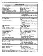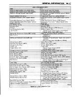
1. Typical VIN
F7557
Figure 2— VIN Location
The gross vehicle weight (GVW) is the weight of the
originally equipped vehicle and all items added to it
after it has left the factory. This would include bodies,
winches, booms, etc., the driver and all occupants, and
the load the vehicle is carrying. The gross vehicle
weight (GVW) must not exceed the gross vehicle weight
rating (GVWR). Also, the front and rear gross axle
weights (GAW) must not exceed the front and rear
gross axle weight rating (GAWR).
The payload rating shown on the label is the maxi
mum allowable cargo load (including the weight of the
driver and all occupants) that the vehicle can carry
based on all factory installed equipment on the vehicle.
The payload rating is reduced if any accessories or
other equipment is added to the vehicle after final date
of manufacture. The weight of these items should be
determined and deducted from the payload rating.
The vehicle may also have a GCWR (Gross Combi
nation Weight Rating). The GCW (Gross Combination
Weight) is the total weight of the loaded tow vehicle
(including passengers) and a loaded trailer.
The tires on the vehicle must be the proper size and
properly inflated for the load which the vehicle is carry
ing. The vehicle certification label shows the original-
ly-equippe d tire size and recom m ended in fla tio n
pressures.
ENGINE IDENTIFICATIO N
NUMBER
The VIN provides engine identification information by
liter and by the engine code letter located on the vehi
cle identification plate.
Stick-on labels attached to the engine, or laser etch
ing or stampings on the engine block, indicate the
engine unit number or date code.
VEHICLE IDENTIFICATION NUMBER (VIN)
Nation of Origin
1 = US Built
2 = Canadian Built
Manufacturers
G=6eneral Motors
Coda
Make
A
Chevrolet Bus'
B
Chevrolet Incomplete
C
Chevrolet Truck
D
G M C Incomplete
J
G M C Bus*
K
G M C M PV
N
Chevrolet MPV
T
G M C Truck
*
Van with 4th Seat
GVWR/BRAKE SYSTEM
Code
GVWR Range Brake System
B
3001-4 000
Hydraulic
c
4 0 0 1-5 000
Hydraulic
D
5001 -6000
Hydraulic
E
600 1-7 000
Hydraulic
F
7001 -8000
Hydraulic
G
6 0 0 1 -9 ,0 0 0
Hydraulic
H
9 ,0 0 1 -10,000
Hydraulic
J
1 0 ,001-14,000
Hydraulic
K
1 4 ,001-16,000
Hydraulic
1
I
4
Code
Series
1
1/2 Ton
2
3/4 Ton
3
1 Ton
8
r
1
Check Digit
Code
Body Type
1
Hi-Cube/Cutaway Van
2
Forward Control
3
Four-Door Cab
4
Two-Door Cab
5
Van
6
Suburban
7
Motor Home Chassis
8
Utility
g
Extended Cab/Van
Line and Chassis Type
Code
Line
C h assis
Type
C
Conventional Cab
4x2
D
Military Truck
4x4
K
Conventional Cab
4x4
G
Van
4x2
P
Forward Control
4x2
S
Sm Conventional Cab
4x2
T
Sm Conventional Cab
4x4
M
Sm Van
4x2
L
Sm Van
4x4
H
Chassis Cutaway
4x2
1
3
r _ [
Production Sequence Number
Code
Year
R
1994
Assembly Plant
B
Baltimore. MD
E
Pontiac, Ml
J
Janesville, Wi
Z
Fort W ayne, Ind.
0
Pontiac, Ml
1
Oshaw a, ON
2
M oraine, OH
3
Detroit, Ml
4
Scarsborough, ON
7
Lordstown, OH
8
Shreveport, LA
Engine Type and Make
C ode
P ro d u cer
Typ e
RPO
4
CPC
2.2L L4 MFI
LN2
F
CPC
6.5L V8 Diesel
L65
H
CPC
5.0L V 8 EFI
L 0 3
K
CPC
5.7L V8 EFI
L 0 5
N
CPC
7.4L V 4 EFI
L19
P
CPC
6 .5 L V8 Diesel
L49
S
CPC
6.5L V8 Diesel
L56
W
CPC
4.3L V 6 CPI
L35
Y
CPC
6 .5L V8 Diesel
L57
Z
CPC
4.3L V 6 EFI
LB4
3700r2986
Содержание Light Duty Truck 1994 Series
Страница 1: ......
Страница 11: ...VIEW A p n n n j VIEW C F7554 Figure 10 Hydra Matic 4L60 E Transmission I D Location ...
Страница 15: ...G VAN MODELS Rally Sportvan Cutaway Van Extended Van Vandura Chevy Van Magnavan Hi Cube Van F7569 ...
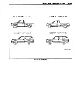
Страница 17: ...S T PICKUP REGULAR CAB 2 DOOR S T UTILITY VEHICLE S T PICKUP EXTENDED CAB 4 DOOR S T UTILITY VEHICLE 2900r4506 ...
Страница 24: ...NOTES ...
Страница 26: ... ...
Страница 69: ...NOTES ...
Страница 71: ...3 2 STEERING ...
Страница 73: ......
Страница 84: ......
Страница 102: ...40 ...
Страница 130: ...NOTES ...
Страница 146: ...NOTES ...
Страница 162: ...NOTES ...
Страница 166: ...Figure 5 Removing the Pinion Flange Figure 6 Pressing the Drive Pinion from the Cage ...
Страница 178: ...Figure 3 Spreading the Differential Case Figure 4 Removing the Differential ...
Страница 190: ...NOTES ...
Страница 202: ...NOTES ...
Страница 206: ...F5785 ...
Страница 209: ...Figure 11 Remove the Pinion Flange F4696 F4759 Figure 14 Removing the Differential Side Bearing ...
Страница 212: ...B Button Moved Out of Bearing Bore F5791 ...
Страница 228: ...NOTES ...
Страница 232: ......
Страница 234: ......
Страница 236: ...Adjuster 63 Bolt 64 Lock Figure 10 Turning the Adjuster Plug K3 Models ...
Страница 237: ...Figure 13 Removing the Pinion Seal 39 Bearing Cup Figure 16 Removing the Inner Bearing Cap ...
Страница 247: ...C Measure with Axle Shaft Forced Outboard 1 Shaft 5 Tube 9 Carrier Connector 23 Output Shaft 29 Carrier Case F5877 ...
Страница 261: ...F7475 ...
Страница 267: ...B Button Moved Out of Bearing Bore F5791 ...
Страница 294: ...NOTES ...
Страница 300: ...NOTES ...
Страница 318: ...NOTES ...
Страница 322: ...SR207LN2 EDS ...
Страница 324: ......
Страница 326: ...OVERHEAD OILING AND RETURN MAIN OIL GALLERY N30005 6A2 J EDS ...
Страница 368: ...103 153 127 V1200 ...
Страница 370: ......
Страница 372: ......
Страница 374: ...F9375 Figure 7 Engine Lubrication Diagram Engines Without Balance Shaft ...
Страница 375: ...Front View Rear View Showing Path Of Oil To Timing Chain Showing Main Gallery Oil Filter And Crankshaft Oil Feed V0575 ...
Страница 376: ...Figure 9 Engine Lubrication Diagram Engines With Balance Shaft ...
Страница 399: ...V2974 ...
Страница 410: ......
Страница 412: ...195 196 201 174 252 163 165 164 244 3706r3924 ...
Страница 452: ......
Страница 454: ...163 164 V1202 ...
Страница 456: ...20 21x 302 210 4 0 41 2 5 2 5 1 2 51 4 2 e3 54 3 9 252 252 S 255 255 25 6 256 209 V1196 ...
Страница 458: ...100 1 8 4 185 183 177 v 75 201 3706r1204 ...
Страница 460: ......
Страница 510: ......
Страница 512: ...V2131 ...
Страница 514: ...110 106 106 103 90 93 89 88 87 86 v 7 7 7 7 j A _ 111 f t 2 a a s 53 49 L 47 46 3706r4751 ...
Страница 516: ...259 260 150 237 S lM 180 167180 J 1 82 183 170 169 1 1 78 1 7 9 213212 2 0 7 205 r i 3706r4752 ...
Страница 566: ...NOTES ...
Страница 574: ...NOTES ...
Страница 618: ...SPECIAL TOOLS ...
Страница 620: ...NOTES ...
Страница 672: ......
Страница 682: ......
Страница 686: ......
Страница 689: ...SPRINGS LOCATED IN THE PUMP PRESSURE CONV CL REGULATOR VALVE SPRINGS LOCATED IN THE VALVE BODY 3 4 SHIFT ...
Страница 694: ...RH0213 4L60 E ...
Страница 695: ...657 659 m i J 8092 H J 34196 4 3 34196 5 657 658 665 J 23907 J 7004 1 J 8092 RH0214 4L60 E ...
Страница 696: ...J 8092 J 34196 4 33 31 J 8092 RH0215 4L60 E ...
Страница 697: ...SPECIAL TOOLS ...
Страница 698: ...SPECIAL TOOLS ...
Страница 758: ...RH0194 4L80 E ...
Страница 764: ......
Страница 770: ...SPECIAL TOOLS ...
Страница 771: ...SPECIAL TOOLS CONT ...
Страница 772: ......
Страница 775: ......
Страница 776: ......
Страница 785: ......
Страница 804: ...NOTES ...
Страница 806: ......
Страница 808: ......
Страница 822: ...3707r5079 ...
Страница 840: ......
Страница 848: ...NOTES ...
Страница 852: ......
Страница 859: ...17 Rear Case Half 18 Oil Pump Pick Up Tube 26 Connector Dowel Pin Location Pump Pick Up Screen F5434 ...
Страница 860: ...F5435 ...
Страница 866: ......
Страница 878: ...F9167 ...
Страница 882: ...16 FrontOutputShaft 18 DrivtQNr 19 DrivenGm t 20 DriveChain 22 FrontOutputBearing V2836 ...
Страница 890: ...F9168 ...
Страница 908: ......
Страница 914: ...J 2619 01 46 Rear Case 85 Front Output Shaft Rear Bearing F7659 Figure 21 Removing the Front Output Shaft Rear Bearing ...
Страница 919: ......


