Fig. 17 Installing Clutch Coil Assembly
Install or Connect
1.
P lace the clutch coil assem bly on the front head with the
term inals positioned at the “m arked” location.
2.
P lace the J 33024 clutch coil installer over the internal
opening o f the clutch coil housing and align installer
w ith the com pressor front head.
3.
C enter the J 8433-1 puller crossbar in the countersunk
center hole o f the J 33024 clutch coil installer. Install the
J 3 4 9 9 2 -2 through bolts and w ashers through the
crossbar slots and thread them , into the holding fixture
J 34992 to full fixture thickness (Fig. 17).
4.
Turn the center forcing screw o f the J 8433-1 puller
crossbar to force the clutch coil onto the front head. Be
sure clutch coil and J 33024 installer stay “in-line”
during installation.
5.
W hen coil is fully seated on the front head, use a 1/8"
diam eter drift punch and stake the front head at three (3)
places 120° apart (Fig. 18), to ensure clutch coil
rem aining in position.
•
Stake size should be only one h alf the area o f the
punch tip and only approxim ately 0 .2 8 -0 .35mm
( .0 1 0 -.0 1 5 " ) deep (Fig. 19).
6.
Install rotor and bearing assem bly and the clutch plate
and hub assem bly according as described previously.
MAJOR V5 COMPRESSOR REPAIR
PROCEDURES
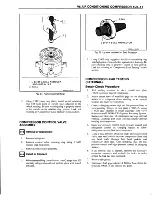
W hen replacing the shaft seal assem bly (Fig. 20),
pressure relief valve or rear head m ounted pressure sw itches
(Fig. 21), even if the com pressor rem ains on the vehicle during
the operation, it will be necessary to discharge the system o f
refrigerant.
O ther than clutch repair procedures, the sam e holds true
for any disassem bly o f the com pressor.
A clean w orkbench covered w ith a sheet o f clean paper,
and a place (clean trays, etc.) for all parts being rem oved and
replaced is im portant, as is the use o f the proper, clean service
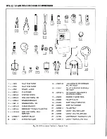
tools.
NOTICE:
A ny
attem pt
to
use
m akeshift
or
inadequate service tools or equipm ent m ay result in
dam age and/or im proper com pressor operation.
1- C L U T C H C O IL
2 - D R I F T PUNCH
3 - S T A K E IN F R O N T
H E A D (3 PLACES)
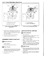
____________________________________________________________ 520016-1D3_________
Fig. 18 Staking Clutch Coil To Front Head
COMPRESSOR SHAFT SEAL
REPLACEMENT
Seal Leak Detection
A shaft seal should not be changed because o f small
am ounts o f oil found on an adjacent surface. The seal is
designed to leak som e oil for lubrication purposes. A shaft seal
should be changed only w hen a large am ount o f sprayed oil is
found, and only after actual refrigerant leakage is found by
using an approved leak detection procedure.
1 - J 8433-3 SCREW
2 - J 8433 PULLER CROSS BAR
3 - J 33024 CLUTCH COIL INSTALLER
4 - CLUTCH COIL ASSEMBLY
__________________________________520015-1D3-R1
Содержание Light Duty Truck 1994 Series
Страница 1: ......
Страница 11: ...VIEW A p n n n j VIEW C F7554 Figure 10 Hydra Matic 4L60 E Transmission I D Location ...
Страница 15: ...G VAN MODELS Rally Sportvan Cutaway Van Extended Van Vandura Chevy Van Magnavan Hi Cube Van F7569 ...
Страница 17: ...S T PICKUP REGULAR CAB 2 DOOR S T UTILITY VEHICLE S T PICKUP EXTENDED CAB 4 DOOR S T UTILITY VEHICLE 2900r4506 ...
Страница 24: ...NOTES ...
Страница 26: ... ...
Страница 69: ...NOTES ...
Страница 71: ...3 2 STEERING ...
Страница 73: ......
Страница 84: ......
Страница 102: ...40 ...
Страница 130: ...NOTES ...
Страница 146: ...NOTES ...
Страница 162: ...NOTES ...
Страница 166: ...Figure 5 Removing the Pinion Flange Figure 6 Pressing the Drive Pinion from the Cage ...
Страница 178: ...Figure 3 Spreading the Differential Case Figure 4 Removing the Differential ...
Страница 190: ...NOTES ...
Страница 202: ...NOTES ...
Страница 206: ...F5785 ...
Страница 209: ...Figure 11 Remove the Pinion Flange F4696 F4759 Figure 14 Removing the Differential Side Bearing ...
Страница 212: ...B Button Moved Out of Bearing Bore F5791 ...
Страница 228: ...NOTES ...
Страница 232: ......
Страница 234: ......
Страница 236: ...Adjuster 63 Bolt 64 Lock Figure 10 Turning the Adjuster Plug K3 Models ...
Страница 237: ...Figure 13 Removing the Pinion Seal 39 Bearing Cup Figure 16 Removing the Inner Bearing Cap ...
Страница 247: ...C Measure with Axle Shaft Forced Outboard 1 Shaft 5 Tube 9 Carrier Connector 23 Output Shaft 29 Carrier Case F5877 ...
Страница 261: ...F7475 ...
Страница 267: ...B Button Moved Out of Bearing Bore F5791 ...
Страница 294: ...NOTES ...
Страница 300: ...NOTES ...
Страница 318: ...NOTES ...
Страница 322: ...SR207LN2 EDS ...
Страница 324: ......
Страница 326: ...OVERHEAD OILING AND RETURN MAIN OIL GALLERY N30005 6A2 J EDS ...
Страница 368: ...103 153 127 V1200 ...
Страница 370: ......
Страница 372: ......
Страница 374: ...F9375 Figure 7 Engine Lubrication Diagram Engines Without Balance Shaft ...
Страница 375: ...Front View Rear View Showing Path Of Oil To Timing Chain Showing Main Gallery Oil Filter And Crankshaft Oil Feed V0575 ...
Страница 376: ...Figure 9 Engine Lubrication Diagram Engines With Balance Shaft ...
Страница 399: ...V2974 ...
Страница 410: ......
Страница 412: ...195 196 201 174 252 163 165 164 244 3706r3924 ...
Страница 452: ......
Страница 454: ...163 164 V1202 ...
Страница 456: ...20 21x 302 210 4 0 41 2 5 2 5 1 2 51 4 2 e3 54 3 9 252 252 S 255 255 25 6 256 209 V1196 ...
Страница 458: ...100 1 8 4 185 183 177 v 75 201 3706r1204 ...
Страница 460: ......
Страница 510: ......
Страница 512: ...V2131 ...
Страница 514: ...110 106 106 103 90 93 89 88 87 86 v 7 7 7 7 j A _ 111 f t 2 a a s 53 49 L 47 46 3706r4751 ...
Страница 516: ...259 260 150 237 S lM 180 167180 J 1 82 183 170 169 1 1 78 1 7 9 213212 2 0 7 205 r i 3706r4752 ...
Страница 566: ...NOTES ...
Страница 574: ...NOTES ...
Страница 618: ...SPECIAL TOOLS ...
Страница 620: ...NOTES ...
Страница 672: ......
Страница 682: ......
Страница 686: ......
Страница 689: ...SPRINGS LOCATED IN THE PUMP PRESSURE CONV CL REGULATOR VALVE SPRINGS LOCATED IN THE VALVE BODY 3 4 SHIFT ...
Страница 694: ...RH0213 4L60 E ...
Страница 695: ...657 659 m i J 8092 H J 34196 4 3 34196 5 657 658 665 J 23907 J 7004 1 J 8092 RH0214 4L60 E ...
Страница 696: ...J 8092 J 34196 4 33 31 J 8092 RH0215 4L60 E ...
Страница 697: ...SPECIAL TOOLS ...
Страница 698: ...SPECIAL TOOLS ...
Страница 758: ...RH0194 4L80 E ...
Страница 764: ......
Страница 770: ...SPECIAL TOOLS ...
Страница 771: ...SPECIAL TOOLS CONT ...
Страница 772: ......
Страница 775: ......
Страница 776: ......
Страница 785: ......
Страница 804: ...NOTES ...
Страница 806: ......
Страница 808: ......
Страница 822: ...3707r5079 ...
Страница 840: ......
Страница 848: ...NOTES ...
Страница 852: ......
Страница 859: ...17 Rear Case Half 18 Oil Pump Pick Up Tube 26 Connector Dowel Pin Location Pump Pick Up Screen F5434 ...
Страница 860: ...F5435 ...
Страница 866: ......
Страница 878: ...F9167 ...
Страница 882: ...16 FrontOutputShaft 18 DrivtQNr 19 DrivenGm t 20 DriveChain 22 FrontOutputBearing V2836 ...
Страница 890: ...F9168 ...
Страница 908: ......
Страница 914: ...J 2619 01 46 Rear Case 85 Front Output Shaft Rear Bearing F7659 Figure 21 Removing the Front Output Shaft Rear Bearing ...
Страница 919: ......


