


Smart Dry Contact Switch 7 - Operating Instructions
4
Device Installation
1)
Make sure the main switch is set to the OFF position
2)
Connect the device based on the diagrams provided
3)
Turn the main switch to the ON position
4)
Include the device in the Z-Wave
™
network
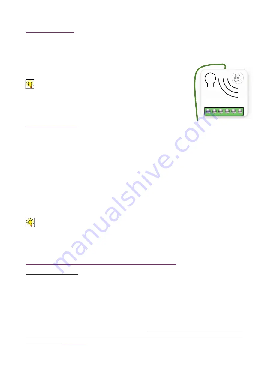
TIP:
The antenna must not be shortened, removed or modified. To ensure maximum
efficiency, it must be installed as shown. Large size metal equipment near the
antenna can negatively affect reception. Each device is a node in a mesh network. If there
are metal obstacles, the obstacle can often be overcome with a further triangulation node.
LED status indicator
The system includes an RGB LED that shows the device’s status during installation:
Solid
RED
: the device is not included in any network
Solid
BLUE
: the device is Offline setup mode state
4 GREEN
blinks then OFF:
the device has been just added to a Z-Wave
™
network in S2 Authenticate Mode
4
BLUE
blinks then OFF:
the device has been just added to a Z-Wave
™
network in S2 Unauthenticated Mode
4
RED
blinks then OFF:
the device has been just added to a Z-Wave
™
network without security
Sequence of
GREEN
-
BLUE
Learn Mode for inclusion
Sequence of
RED
-
BLUE
Learn Mode for exclusion
Rapid sequence of
GREEN
-
BLUE
-
RED
: the event on the input (
external switch
) is not valid
TIP
: To test if the electrical connections are correct, before the inclusion of the device, while pressing
n
times the
external switch, the RGB LED should flash
green
for the same amount of times. If it does not, check the wire
connections.
Add/Remove the device into a Z-Wave
™
network (classic)
Standard Inclusion (add)
All Smart Serie 7 devices are compatible with all Z-Wave
™
/Z-Wave Plus
™
certified controllers. The devices support both
the
Network Wide Inclusion
mechanism (which offers the ability to be included in a network, even if the device is not
directly connected to the controller) and
Normal Inclusion
.
By default, the inclusion procedure starts in
Normal Inclusion
mode and after a short timeout the procedure continues
in
Network Wide Inclusion
mode that lasts for about 20 Seconds.
Only a controller can add the device into the network. After activating the inclusion function by the controller, the device
can be added by setting it in
Learn Mode
.
Before including the device, the LED status indicator is solid RED. The adding of a device is executed by activating the
adding procedure in the inclusion section of the controller interface and executing 1 or 3 click on the integrated
button
(the device is set in
Learn Mode
). As soon as the inclusion procedure initiates the LED indicator starts a sequence of
GREEN-BLUE blinks. The device is included in the network when the LED status is OFF and the interview is completed.
1 2 3 4 5 6


