background image

4

ENGLISH

01

06

03

02

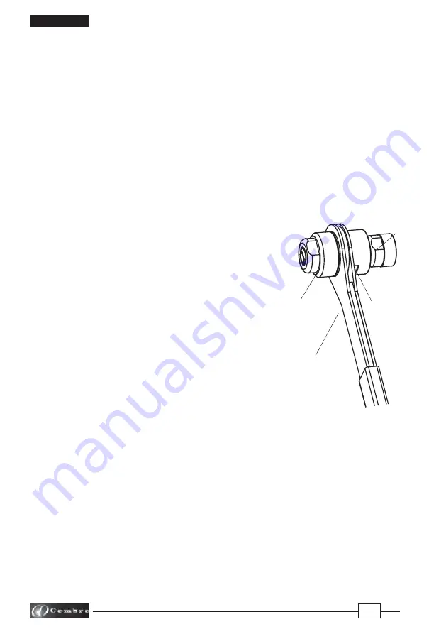
FIG. 2

3.  INSTRUCTIONS FOR USE

3.1) Setting  

(Ref. to Figs. 2 - 7)

–  Drill rail web or, 

if already drilled, use a suitable tool to clean the hole 

(Fig. 3).

–  Check the size of the hole with the "GO/NO GO" gauge 

CAL ....

;


the hole size is correct 

only if the 

  green part enters the hole

. If the red part enters, the hole is too large (Fig. 4).

– Insert the 

AR...-1 

copper bush into the rail hole (Fig. 5).

–  Turn, anti-clockwise, the support (06) up to the automatic stop (Fig. 2).

  In order to achieve the maximum possible stroke length, the support (06) must be completely 

  turned (anti-clockwise) up to the mechanical stop.  

–  Insert the calibrated plunger 

OG 6.5

 into the bush, on the fl ange side ( Fig. 6).

–  Using the recess in the gauge 

CAL ....

 screw and tighten the plunger 

OG 6.5

 into the tool (Fig. 7).

3.2) Extrusion

  (Ref. to Figs. 2; 8; 9)

Before proceeding to the extrusion process, make sure 

that the calibrated plunger is fully screwed in the tool 

housing.

–  Operate the tool, to pull the plunger 

OG 6.5 

through 

  the bush and extrude the bush onto the sides of the 

  hole (Fig. 8), the bush will also extrude itself around the 

  opposite side of the rail web (Fig. 9).

  Should the calibrated plunger not fully exit from the 

  bush and the tool remain blocked, please proceed as 

 follows:

–  Unscrew and remove the adjustment locking ring (02).

–  Remove, reverse and refi t the ratchet handle (01).

–  Manually grip the support (06) and rotate the ratchet 

  handle (01) anti-clockwise, up to the automatic stop.

–  Turn the support (06) in a clockwise direction up to the automatic stop.

–  Turn the nut (03) in a clockwise direction until the support (06) butts fi rmly against the rail web.

–  Remove, reverse and refi t the ratchet handle (01) back to the original position.

– Refi t and tighten the adjustment locking ring (02).

  Rotate the ratchet handle (01) in a clockwise direction to complete the installation of the contact 

 bush. 

Содержание MTE1-S

Страница 1: ...AGEVON SCHIENENKOTAKTE HERRAMIENTA MEC NICA MANUAL PARA LA INSTALACION DE LOS KITS DE CONEXION ELECTRICA UTENSILE MECCANICO MANUALE PER L INSTALLAZIONE DI CONTATTI ELETTRICI 01 M 078 OPERATION AND MAI...

Страница 2: ...Prima di utilizzare l utensile leggere attentamente le istruzioni contenute in questo manuale 2 When operating keep hands away from the danger zone En cours d utilisation tenir les mains loign es de...

Страница 3: ...applications Dimensions length 315 mm width 58 mm Weight 1 3 kg 2 MTE1 SYSTEM Ref to Fig 1 The MTE1 system consists of a Hand tool type MTE1 S b n 2 plungers type OG 6 5 c n 1 gauge type CAL 95 10 for...

Страница 4: ...to the extrusion process make sure that the calibrated plunger is fully screwed in the tool housing Operate the tool to pull the plunger OG 6 5 through the bush and extrude the bush onto the sides of...

Страница 5: ...ctor Assemblethelugtothe angeofthebushovertheprotruding bolt Fit the at washer and the self locking nut Fig 11 5 WARNING The tool is robust and requires very little daily maintenance Compliancewiththe...

Страница 6: ...rails Dimensions longeur 315 mm largeur 58 mm Poids 1 3 kg 2 REFERENCE MTE1 Voir Fig 1 La r f rence MTE1 comprend a Outil mecanique manuel r f MTE1 S b 2 extrudeurs r f OG 6 5 c 1 calibre de contr le...

Страница 7: ...el outilens aidantducalibre CAL Fig 7 3 2 Extrusion Voir Fig 2 8 9 Enpr alable veiller cequel extrudeursoitcompl tement viss dans le logement de l outil Actionner l outil de sorte que l extrudeur OG 6...

Страница 8: ...uccessivement sur le boulon la cosse la rondelle et serrer l crou autofrein Fig 11 5 ENTRETIEN Cet outil est robuste et ne n cessite aucune attention ou entretien particulier Les recommandations qui s...

Страница 9: ...eite 58 mm Gewicht 1 3 kg 2 SYSTEM MTE1 Siehe Bild 1 Die Bestandteile des System MTE1 sind a Mechanisches Handwerkzeug Typ MTE1 S b 2 St ck Spreizdorne Typ OG 6 5 c 1 St ck Ausschu lehre Typ CAL 95 10...

Страница 10: ...CAL in das Gewinde des Werkzeug eingeschraubt Bild 7 3 2 Einzugsvorgang Siehe Bild 2 8 und 9 Vor jedem Einzugsvorgang hat man zu kontrollieren dass der Spreizdorn vollst ndig im Zugzylinder eingeschra...

Страница 11: ...esch digungen wie Stoss und Staub gesch tzt Die Segeltuchtasche Typ CVB 016 hat die Abmasse 350x130mm und ein Gewicht von 0 14 kg geeignet zum lagern Werkzeug Ausschu lehre und 2 St ck Spreizdorne 6 E...

Страница 12: ...ongitud 315 mm anchura 58 mm Peso 1 3 kg 2 SISTEMA MTE1 Ref a Fig 1 Se indica Sistema completo MTE1 el conjunto de a Herramienta mec nica manual tipo MTE1 S b n 2 pasadores calibrados tipo OG 6 5 c n...

Страница 13: ...deextrusi nasegurarsede que el pasador est atornillado completamente en la sede de la herramienta Accionarlaherramientaqueaplicar unafuerzaquepermitir raccionar el pasador dentro del contacto d ndole...

Страница 14: ...u bolsa de tela de cierre herm tico Dicha bolsa mod CVB 016 de dimensiones 350x130 mm y peso 0 14 kg contiene la herramienta el calibre y dos pasadores calibrados 6 LISTA DE COMPONENTES Ref a Fig 12 7...

Страница 15: ...m larghezza 58 mm Peso 1 3 kg 2 SISTEMA MTE1 Rif a Fig 1 Si de nisce Sistema completo MTE1 l assieme costituito da a Utensile meccanico manuale tipo MTE1 S b n 2 ogive calibrate tipo OG 6 5 c Calibro...

Страница 16: ...one Rif a Figg 2 8 9 Prima di procedere alla successiva fase di estrusione assi curarsi che l ogiva sia avvitata completamente nella sede dell utensile Azionare l utensile Viene esercitata in questo m...

Страница 17: ...5 AVVERTENZE L utensile robusto e non richiede attenzioni particolari per garantirne un corretto funzionamento baster osservare alcune semplici precauzioni 5 1 Accurata pulizia Tenere presente che la...

Страница 18: ...18 FIG 3 FIG 4 FIG 7 FIG 6 FIG 8 FIG 5 OK NO FIG 9...

Страница 19: ...19 10 03 06 08 05 02 04 01 09 07 FIG 12 LONGITUDINAL SECTION COUPE LONGITUDINALE SCHNITTZEICHNUNG SECCION LONGITUDINAL SEZIONE LONGITUDINALE FIG 10 FIG 11...

Страница 20: ...k Cembre S p A Via Serenissima 9 25135 Brescia Italia Telefono 39 030 36921 Telefax 39 030 3365766 E mail sales cembre com www cembre com Cembre S a r l 22 Avenue Ferdinand de Lesseps 91420 Morangis F...

Отзывы: