background image

365

UPO33

27<<

>>28

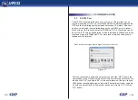
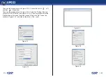
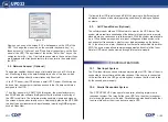
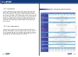
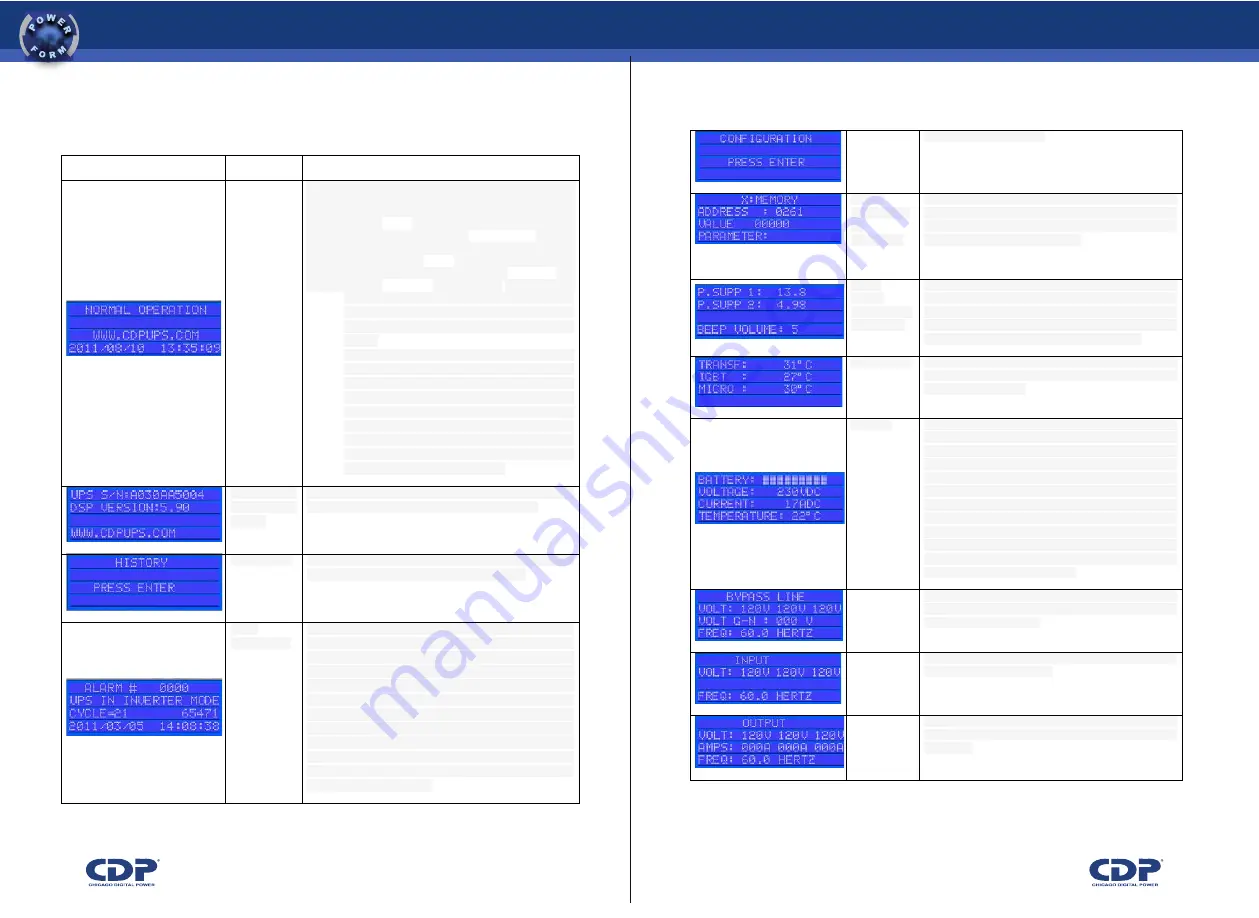
7.4 table UPS’s menu description

!

EB8F;<D?#>;B8!

allowed in the setup menu.

!

!

!

!

values 
of configurati
on 
parameters

!

this  menu may  change the  operating  parameters of 
the ups. since  the  change of  these  parameters can 
cause  serious damage  to  the ups,  only qualified 
personnel can make modifications.

!

!

supply 
voltage 
and volume o
f the whistle

!

indicates  the dc voltages that  supply  the electronic 
control  of the ups. it  also indicates  the  volume  of the 
alarm. to change the volume of the alarm, press "enter 
/ esc  button" three  times  and  then vary the  volume 
with "arrow up" to up and "down arrow" to down.

!

!

temperatures

!

this  display  indicates the  temperature  of critical 
devices within 

the ups 

(transformer, 

igbt's, microcontroller).

!

!

batteries

!

this  screen  shows  the battery  status:  percentage 
of load,  voltage, current and  temperature. in  this  menu 
you can  perform  a battery  test, press  three  times to 
do the 

"enter 

/ esc 

button". the duration 

of 

the test depends  on  the  configuration (default is  one 
minute). if the end of the test result is satisfactory, there 
is 

no display on 

the 

lcd 

and an 

alarm will 

occur "battery test ok",  which can  be  seen  in the  alarm 
history. if  the result  is  not  satisfactory to  generate 
the alarm "battery test failure", which is displayed on the 
screen and 

stored 

in 

the 

alarm 

history. the battery led will be red.

!

!

V$A#@@!

indicates the  status  of  the bypass input:  voltage in  the 
three 

phases of 

the bypass input, 

voltage and 

frequency neutral ground.

!

!

;8AD>!

indicates the status of the ups input: input voltage on all 
three phases and frequency.

!

!

!

BD>AD>!

indicates  the output  status of  the ups in  the  three-
phase voltage,  current in  all  three  phases and 
frequency.

!

!

Table 5.2. Description of the UPS’ menus 

0#<%./#-.-#+,!

,.='!

4'<E&#H-#+,!

!

C#;8!CJ8D!

This  is  the main  menu display. this  screen shows 

the ups operating  status (in  this case  is  in normal 

operation).it 

also displays the 

web 

address 

of manufacturer,  date and  time. in  this  menu  you can 

also  update  the date  and  time,  to  make  it do  the 

following: 

 press three times the "enter / esc button", and the last 

two digits  of  the  year start  to  flash,  change the 

year using the "arrow" and "down arrow ".


• when you

 set the year again press "enter / esc  

button" and the number for the month will flash, 
change the month using the "arrow" and "down 
arrow". 

•  press  again

 "enter  / esc", and  the  number for 

the  day will  flash. change  the day  with  "arrow" 
and "down  arrow".  to  change  the  time simply 
press "enter  / esc  button" and  modify  it with 
"arrow" 

and "down 

arrow" 

•  press

 again "enter  / esc  button" and  may 

amend the  minutes to  "arrow"  and "down 
arrow". return to  press "enter /  esc  button"  and 
the date and time will be updated.

!

!

serial number 
and firmware 
version

!

this  screen shows  the serial computer, the  firmware 
version of the ups and contact the manufacturer.

!

!

alarm history

!

this  screen  allows entry  into  the alarm  history. to  view 
the history you must press "enter / esc button"

!

!

alarm 
history detail

!

on  this  screen you  can  see  information about  the 
latest alarms have  been  activated  in the ups. for 
information  about other  alarm press  the  "arrow" 
or "down arrow". in the first line is the order in which the 
alarm  occurred  alarm 000 being  the most  recent. the 
second  line shows  the cause  of  the  alarm (In  table 
7.1 there  is  more  information about  alarms that  may 
occur). the fourth line displays the date and time of the 
event. the  third  line  shows  the  number of cycles  of 
the output 

waveform, 

which 

went before 

the 

occurrence of  the  event  and after  the  time  that is 
recorded in the fourth line.

!

Содержание UPO33

Страница 1: ...ual Three PhaseUPS WithIntegratedMonitoringSystem CHICAGO DIGITAL POWER Chicago Digital Power Incorporated 1193 W Higgins Elle Groove Village Il 60007 Tel 847 718 9545 Fax 847 718 9546 www cdpups com 365 UPO33 ...

Страница 2: ...r to implementation 6 OPERATING PROCEDURES 6 1 Comissioning 6 2 Total Shutdown 6 3 Normal to electronic bypass transference 6 4 Manual Bypass 6 5 Alarm Reset 7 OPERATION 7 1 Control Panel 7 2 Front cover lights 7 3 LCD operation 7 4 UPSmenudescription 27 7 5 Emergency shutdown 8 ALARMS 8 1 Active alarms 8 2 Alarm reset and UPS normalization 9 COMMUNICATIONS 9 1 RS 232 port 9 2 Net adapter Optional...

Страница 3: ... upright Upon receipt of the check the packaging machine which must be in perfect condition no hits no breaks free from excessive moisture otherwise immediately notify the carrier and our company During storage of ups it must be placed in a suitable place where not exposed to direct sunlight or near heat sources such as boilers stoves etc As one should not store near water pipes or in wet envi ron...

Страница 4: ... the fit of connectors Here are some safety recommendations during installation operation and maintenance of the UPS All work must be intervention at UPS Realize by qualified personnel Prior to installation of the equipment must verify that all breakers are in the OFF position mainly batteries and must be handled only when the UPS is completely interconnected to rush for strict compliance to the p...

Страница 5: ...ver Lights Communication ports RS232 and RJ 45 optional Cooling slots Frontal Panel Lock Front cover lights Communications ports RS232 and RJ 45 optional Cooling Slots Transient supressor Dual Input bypass breaker Optional Input breaker Output breaker Manual bypass breaker Battery breaker Transient supressor Dual input bypass breaker Optional Input breaker Output breaker Manual bypass breaker Batt...

Страница 6: ...KJ B 9 EB88JE J9 B KJ C 8 K BD K 8 J JE B8 E U EK V J9 B8 2 d 0KJ K BAJ B8 CB9J UKJ8 KJ J U BCJ B BF BTJ B 9 KJ BD AD KJ J U J J 89 VBTJ KJ 8BC 8 T DJ BF BAJ B8 B KJ V J VJ8EK BB CDEK 9 EK J9 1IFD 8 C 8D V A CB9J UKJ8 KJ B 9 EB88JE J9 9 JE B KJ C 8 K BD K V A E ED K J KJ G42 J F JC 8 D8J8J XJ9 0K CB9J BU KJ D J B BAJ B B E BD E J B GJ 1IFD 18 K BAJ B8 CB9J KJ B 9 EB88JE J9 B KJ C 8 K BD K 8 J JE B...

Страница 7: ... inside the UPS is above the nominal value of operation or when the battery pack is deeply discharged In this state the load is powered from the network through the bypass breaker When the UPS is in manual bypass the load is supplied directly from the network through the bypass breaker while the UPS remains de energized This allows maintenance on the UPS without interrupting power to the load In f...

Страница 8: ... the input of the UPS before the bat estuaries discharge 5 Press the OFF for five seconds 6 Press the ON for more than six seconds 7 See procedure in Section 6 4 8 See procedure in Section 6 4 9 See procedure in Section 6 2 10 See procedure in Section 6 1 11 Turn off the bypass breaker 12 Switch the bypass breaker 13 When it returns to the input energy and the batteries are discharged 14 See proce...

Страница 9: ... 208 VAC There must be a unique breaker to the UPS distribution panel Each line entry and exit should have adequate thickness to withstand the current passing through it The current driving the UPS and hence the sizes of the wires at the entrance and exit agreements changes do to their ability as shown in the following tables FIGURE 4 1 UPS PACKAGING FIGURE 4 2 UPS ANCHORED TO THE PALLET 1 A79 ABC...

Страница 10: ...itches are turned off Check that all loads are off Check the polarity of the battery bank h We recommend using a three phase industrial breaker GHEEBGFDHE FBA2DEIJ9 To access the terminals in the ups of 20 kva to 30 kva remove the back cover the terminals are at the bottom in the ups of 40 kva to 80 kva the terminals are located on the front face to access them you must first open the front cover ...

Страница 11: ...ILURE and you will hear a beep If this is the case check that batteries are properly connected and the battery breaker is on If when installing the UPS was an error in the phases connection turning on the UPS on the screen appears an alarm FAILURE SEQUENCE BYPASS In this case the UPS will not operate in bypass mode but it will operate in normal mode of operation To solve the problem correctly conn...

Страница 12: ...have the correct polarity Turn the output breaker At this point will begin to supply the load through the bypass Turn the manual bypass breaker For the UPS is operating in normal mode press the ON for more than a second It is recommended that the bypass breaker manipulation is done by quali fied personnel 6 5 Alarm Reset See section 8 2 The UPS UPO33 includes a control panel that displays the stat...

Страница 13: ...he lights are reds means that the load is being fed to the energy stored in batteries if the lights are flashing red and blue is because the charger is not working properly the cause may be who missed one or two phases to the entrance when the charger starts and if there is no problem the lights are flashing blue and violet if you used the emergency shutdown of the ups the light has a violet color...

Страница 14: ... batteries IF the lights are flashing red and blue is because the charger is not working properly The cause may be that missed one or two steps at the entrance When the charger starts and there is no problem if the lights are flashing blue and violet If you use the emergency shutdown of the UPS the light has a violet color 7 3 LCD operation In Figure 7 2 illustrates the operation of the LCD and in...

Страница 15: ... all three phases and frequency Table 5 2 Description of the UPS menus 0 4 E H C 8 CJ8D This is the main menu display this screen shows the ups operating status in this case is in normal operation it also displays the web address of manufacturer date and time in this menu you can also update the date and time to make it do the following press three times the enter esc button and the last two digit...

Страница 16: ...and the batteries are discharged the causes may be dc fuse open loss of any of the input phases input voltage phase neutral outside the operating range 80 to 150 volts rms check the input voltages call for service RECTIFIER TURN ON is on the battery charger 8 INVERTER TURN ON The invertir is turned on 8 MANUAL INV SHUTDOWN inverter has been turned off manually 8 EMERGENCY PWR OFF emergency shutdow...

Страница 17: ...D the ups batteries are depleted one possible cause is that the ups has operated in battery mode for long wait for the ups input is normal and start charging the batteries if after the input is normal the battery will not charge call service DC FUSE BLOWN the dc fuse is open this happens when you turn the battery breaker before you turn on the charger when you are starting the ups support call 5 V...

Страница 18: ...battery warning 8 CHECK FANS the blowholes are more than 5 years of use it is advisable to change the FANS to perform the operation contact technical support SELFDIAGNOSTIC alarm information indicates that event counters ups have flooded the memory limit note this does not imply a malfunction of the machine diagnostic is recommended by software call support PWR SUPPLY WARNING it is activated when ...

Страница 19: ...ppears when you turn on the ups 8 TEMPERATURE ALERT this alarm occurs when there is a high temperature in the computer but not high enough to go to bypass check the temperature of where the ups is located check the air conditioning system because it may be a fault AMBIENT TEMP OK it is activated when the temperature is at an optimum level after having been high 8 START BATTERY TEST has been initia...

Страница 20: ...inverter overflow of the investor check for shorts to the output verify that the load does not consume more power than it is capable of supplying the ups check the temperature of where the ups is located avoid charges that generate large surges in short time if the problem persists call service Ij4 3 Q G0 3 L the frequency of the input bypass is not adequate to power the loads wait until the frequ...

Страница 21: ...nd using a USB to serial converter TRENDnet TU S9 Monitoring can be done from a PC using HyperTerminal which is included in Windows versions less than or equal to Windows XP For more recent versions can be down loaded from the Internet Give the connection a name and select an icon and click OK Then in the next window in the Connect using select the port where the UPS is connec ted and click OK see...

Страница 22: ...1 4 Click on the button off and then Properties Then see the window shown in Figure 9 1 5 Select the Settings tab and click on the ASCII Setup see Figure 9 1 6 In the next window select the Add linefeed at the end of each line received and click OK to see the window in Figure 9 1 4 and click on the button call ...

Страница 23: ...s Additionally provide the UPS MIB to adapt to an environment with a professional monitoring NMS program such as OpenView If allowed the UPS is able to send E MAIL s warning to 8 different email addresses in case of abnormal operating conditions including cell phone numbers The cellular modem allows a GSM network to monitor the UPS status This system allows real time knowledge of the behavior of e...

Страница 24: ... normally closed switch thus complementary signals For example when the UPS inverter is operating normally the normally open switch is open and normally closed switch is closed If the inverter fails the normally open switch closes and the normally closed switch will open With the ability to customize the UPS is easy to adapt the UPS to the particular characteristics of virtually any power plant Th...

Страница 25: ...oundingsystemgenerally verifyingthattheneutralofthetransformersecondaryoverallsystempowerisreferenced tothispoint Theinputandoutputconductorsmustberoutedtogethertoavoidfeedback andachieveelectromagneticcompatibility Itmustestablishthattheminimumdistancesofventilation maintenanceandoperationof theUPStothewallsorbarriersaround mustbeatleast500mm 50cm Theboardshouldhavearegulatedinsulatedneutralbusba...

Страница 26: ...ls parts components and labor II CHICAGO DIGITAL POWER OF MEXICO SA DE CV will repair the product and if your judgment is not beyond repair to change the team and the defective parts and components thereof without charge to the owner during the warranty period and the cost reasonably incurred transportation of the product resulting from compliance III The repair time will not exceed thirty days fr...

Отзывы: