Cavitar C300 Скачать руководство пользователя страница 28


26 

Gain can be applied in order to make the image brighter. However, large gain values will 
increase the noise in the images. Gain is typically applied if the original image is too dark. 
This can be the case with very dark or highly reflective metal surfaces. 

Gamma is a nonlinear correction tool that can increase the visibility of dark regions with 
respect to the brighter regions. Gamma correction can often improve the visual appearance of 
the image.  

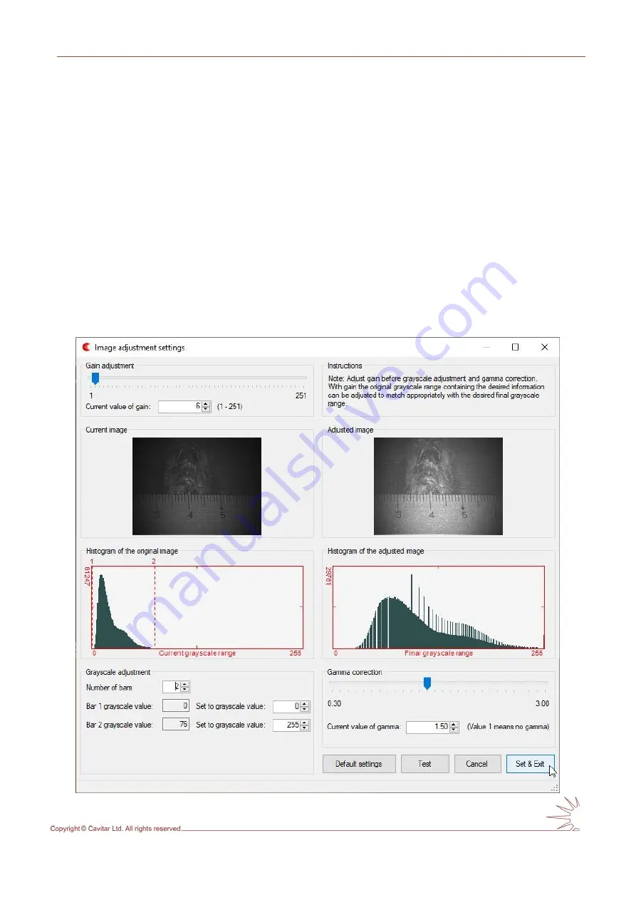
Grayscale adjustment can be used for selecting desired ranges of grayscale values that will be 
displayed on the screen as different ranges of grayscale values. This can have a big effect on 
the appearance of the image. As an example, one can assign a larger range for the interesting 
grayscale values and a smaller range for the less interesting grayscale values. The desired 
ranges can be set by moving the vertical red bars below the left-hand image (“Current 
image”). This is shown in Fig. 5.14, where bar 2 has been moved leftwards in such a way that 
original grayscale range 0…76 will be scaled to new grayscale range 0…255. After pressing 
“Test” button the effect can be seen in the “Adjusted image” and “Histogram of the adjusted 
image”. 


Fig. 5.14. Desired grayscale ranges selected. 

Содержание C300

Страница 1: ...CAVITAR Welding Camera C300 Operating Manual ...

Страница 2: ...uidelines 27 5 2 7 Calibration 29 5 2 8 Recording settings 33 5 2 9 Recording images 34 5 2 10 Viewing and saving recorded images 34 5 2 11 Snapshot 36 5 3 STARTING AND STOPPING LASER ILLUMINATION 37 5 4 AFTER OPERATION 37 5 5 TROUBLESHOOTING 38 6 MAINTENANCE AND SERVICE INFORMATION 39 7 SUPPORT AND END OF LIFE 40 8 LIMITED WARRANTY 41 Cavitar Welding Camera model C300 Cavitar product code A040 Op...

Страница 3: ...on The laser source of the system doesn t require any control by the operator Therefore from the operation point of view the system doesn t differ from a normal machine vision camera system Welding Camera is a class 3R laser product with a nominal ocular hazard distance NOHD of 3 meters Please read this operating manual carefully before using Welding Camera Chapter 2 contains important safety info...

Страница 4: ...s indicated by the warning label on top of the camera unit see the label above o laser aperture is indicated by the yellow aperture label on top of the camera unit see the label above o Nominal Ocular Hazard Distance NOHD is 3 meters Do not look into the direct reflected or scattered laser beam o camera unit emits visible red laser light at 645 10 nm wavelength band o laser beam is emitted from th...

Страница 5: ...em especially the signal inputs to electrical shock or static discharge as this can create a risk of unintended laser emission resulting in eye hazard o Excessive vibration or strong mechanical impact may damage the equipment o The operating temperature of Welding Camera is 10 40 C with proper mounting Do not expose the device to excessively low or high temperatures without appropriate means for c...

Страница 6: ...ds IEC 61326 1 2020 Immunity in an industrial electromagnetic environment CISPR 11 2015 AMD2 2019 Group 1 Class A emissions FCC 47 CFR Part 15B Class A emissions ICES 003 Issue 6 Class A emissions Group 1 equipment is any industrial scientific or medical equipment that does not intentionally generate radio frequency energy in the frequency range 9 kHz to 400 GHz for the treatment of material or in...

Страница 7: ...including 1 2 m long fixed cable CABLES GigE cable between camera unit and computer standard length 10 m power cable between camera unit and power supply standard length 10 m power supply cable between power supply and AC mains standard length 2 m ACCESSORIES 2x spare protective window 2x cooling hose connector with O ring 2x thermally conductive sheet to be used between camera and mounting INSTAL...

Страница 8: ...ard distance NOHD 3 m Electrical Power supply input voltage AC 100 240 V 47 63 Hz Power supply output voltage DC 24 V Power supply power rating 25 VA Mechanical Camera unit dimensions W x H x L 30 mm x 45 mm x 99 mm excl connectors Camera unit weight 300 g Camera unit attachment 4 x M4 and 6x M3 mounting threads Environmental Storage temperature 0 50 C Operation temperature 10 40 C 1 Indoor outdoo...

Страница 9: ...a safe temperature for the coolant to enter the camera ii Ensure continuous and sufficient flow of the coolant a clear warning is needed if the flow is reduced stopped in order to avoid damage to the camera iii Carefully insulate the camera and the cables from the environment e g with appropriate thermally insulating protective sleeves Also place the cooling hoses inside the same protective sleeve...

Страница 10: ... 1 Camera unit top view fixed working distance version Fig 3 2 Camera unit top view adjustable working distance version Fig 3 3 Camera unit front view Fig 3 4 Camera unit back view A B C D E F G H I K A B C J ...

Страница 11: ...document Working distance adjustment instructions E Protective window holder rotate to change the replaceable protective window F Mounting threads 2x M4 see Fig 3 5 for more details G Power led H Connector for power cable I Connector for GigE cable J Threads 2x M6x0 75 for air or liquid cooling K Chassis ground 2x M4 mounting threads Fig 3 5 Camera unit mechanical drawing Fig 3 6 Bottom view of th...

Страница 12: ... than the supplied power supply to the camera unit Only connect the power supply to a wall socket with protective grounding Power supply can be disconnected from the mains supply by removing the power supply plug from the wall socket ...

Страница 13: ...to the same computer Ventilation Efficient ventilation to prevent heating If applicable please uninstall old software version completely before installing new software version Insert the CAVITAR Capture software CD into the CD drive and run the setup file if the setup doesn t start automatically In some cases it may be necessary to disable firewall and or virus software As an example in Windows 10...

Страница 14: ...12 Fig 4 2 close all other applications and click Next to start installation Fig 4 3 Click I Agree to continue ...

Страница 15: ...for two cameras if two systems will be used with the same computer Welding Camera has GigE interface so USB camera drivers are usually not needed Click Next to continue Fig 4 5 Choose install location and click Next to continue ...

Страница 16: ...14 Fig 4 6 Choose start menu folder and click Install to continue Fig 4 7 After installation is completed click Next to continue ...

Страница 17: ...he area between camera side s and mounting The mounting should be made of material with high thermal conductivity such as aluminium If active cooling is applied connect the cooling connectors see Fig 4 9G to the threads of the camera unit see Fig 3 4J ensure the O rings are in place maximum torque 0 1 Nm and attach appropriate cooling system air or liquid to the connectors suitable for hoses with ...

Страница 18: ...er cable see Fig 4 9A between camera unit see Fig 3 4H and power supply unit see Fig 4 9B connect the power supply cable see Fig 4 9C to the power supply connect the GigE cable see Fig 4 9D between camera unit see Fig 3 4I and computer computer is not included in the standard system ensure the camera unit housing is firmly connected to ground see Fig 3 4K Fig 4 9 shows the welding camera system af...

Страница 19: ... are such that neither the operator nor anybody else can be accidentally exposed to laser radiation Pay special attention to the placement of camera unit and computer Ensure that all system components are placed in such a way that the applicable mains plugs are always easily removable from the electrical network ...

Страница 20: ...ograms do not prevent the use of CAVITAR Capture Welding Camera contains a GigE camera with a GigE interface In some cases the following actions may be needed disconnect any network connections the computer may have Also wireless networks should be disabled if firewall and virus protection settings need to be relaxed adjust firewall and virus protection settings in such a way that all network traf...

Страница 21: ...rocedure will start see Figs 5 1 5 5 Proceed by following the instructions and email the registration file to Cavitar Fig 5 1 Registration step 1 Fig 5 2 Registration step 2 Fig 5 4 Registration file saved notification Fig 5 3 Registration step 3 Fig 5 5 Registration final notification ...

Страница 22: ...e The screen shown in Fig 5 1 will appear Click Load and select the file sent by Cavitar After this a notification appears see Fig 5 6 and CAVITAR Capture starts after pressing OK see Fig 5 7 Fig 5 6 Registration completed successfully Fig 5 7 CAVITAR Capture user interface ...

Страница 23: ...ously selected camera is connected to the computer there should be no need to repeat this procedure Select Open Camera from File menu This will open the window shown in Fig 5 8 Select the correct camera and click OK if the camera hasn t been found by Windows there will be no camera in the Select a camera to open list A view as in Fig 5 9 will appear Fig 5 8 Opening the camera Fig 5 9 View after ca...

Страница 24: ...ding to recording settings D Tag field text in this field is added to recording destination folder and file names E Zoom controls for adjusting the size of the image on screen F Preview controls for adjusting the image refresh rate on screen G Gain control for adjusting the brightness of the image H Guideline buttons for adding horizontal or vertical guidelines I Image resolution and bit depth inf...

Страница 25: ... Show statusbar Show capture frame rate Show recording controls Show sources Show camera capture rate tune controls Show histogram View grid Rotate image by 90 degrees Fullscreen mode Alt Enter Autofit image for fullscreen mode Show zoom controls in fullscreen mode Settings Snapshot Recording Camera Image adjustment Calibration Guideline and grid properties Help Registration information Language A...

Страница 26: ...er set Camera capture rate e g to 25 fps or your preferred frame rate up to 60 fps set Sync mode to internal o the use of external sync mode e g synchronization to arc requires a special power sync cable instead of the standard power cable o if external sync mode is used select correct Sync polarity o external sync signal 0 4 5V low 11 24V high input impedance 680 ohm set Sync out to Off o the use...

Страница 27: ...y o Note if 2x2 binning is applied the exposure time must be set to at least 8 s in order to see laser illumination in the images Recommended exposure time with 2x2 binning is 9 s or 10 s Mirror and Flip for changing the orientation of the image 5 2 5 Image adjustment Image adjustment tool can be used for optimizing the visual appearance of the image Image adjustment window can be opened by select...

Страница 28: ...es of grayscale values that will be displayed on the screen as different ranges of grayscale values This can have a big effect on the appearance of the image As an example one can assign a larger range for the interesting grayscale values and a smaller range for the less interesting grayscale values The desired ranges can be set by moving the vertical red bars below the left hand image Current ima...

Страница 29: ...es can be drawn on top of the image These guidelines can be used for e g ensuring that the welding torch follows the correct path Together with the calibration feature described in Section 5 2 7 in more detail guidelines also enable measurements from the images in real time In order to add horizontal guidelines click X button see Fig 5 10H Vertical guidelines can be added by clicking the Y button ...

Страница 30: ...28 Fig 5 16 Guideline and grid properties ...

Страница 31: ...s and calculated distances on the screen Grid spacing and precision Fig 5 17 shows the view after selecting lines for 1 and 2 and pressing OK in Fig 5 16 Fig 5 17 Guidelines with calculated distances 5 2 7 Calibration Calibration feature enables the calibration of the image so that instead of pixel values it is possible to get actual measures from the images in the desired unit e g mm To calibrate...

Страница 32: ...tern or some other object with known dimensions Once the lines are positioned to known distances from each other these distances are typed to the appropriate fields Calibration based on conversion can be made without guidelines In Fig 5 17 a ruler was applied to position the vertical lines 20mm apart from each other The distance between horizontal lines was made equal to the distance between verti...

Страница 33: ...sing Change file path button After all information has been successfully filled the Calibrate button becomes active and the calibration can be completed A confirmation window will appear after pressing Calibrate button Fig 5 20 Fig 5 20 Calibration complete window Fig 5 21 shows the view after successful calibration As can be seen the distances between the vertical and horizontal lines are now in ...

Страница 34: ...32 Fig 5 21 View after calibration ...

Страница 35: ...tings To define the recording settings select Recording from Settings menu This will open the window shown in Fig 5 22 The actual appearance of the window may depend on the software version in use Fig 5 22 Recording settings ...

Страница 36: ...lected images will be saved in RAM memory Various options can be selected with RAM recording If not selected images will be saved on hard disk under Recorder root folder o Do not update display while recording selecting this option frees PC resources if needed 5 2 9 Recording images Recording is started by pressing REC button see Fig 5 10C This will start recording according to the recording setti...

Страница 37: ...ll as the Export button for saving the images to a desired location have been indicated in Fig 5 23 It is also possible to move the slider with a mouse If some or all of the recorded images need to be saved on a hard disk the Export button needs to be pressed This opens the Export window Fig 5 24 ...

Страница 38: ...to be saved choose whether the frames will be saved as separate files or as a video add a folder tag if desirable view and modify if needed the recording settings 5 2 11 Snapshot Snapshot means the capture of a single frame Snapshot can be taken by pressing the Snapshot button on the left hand side of the REC button see Fig 5 10C Before taking snapshots it is good to set the snapshot settings by s...

Страница 39: ...ngs menu Camera To stop laser illumination and image acquisition press Stop button Fig 5 10A disconnect the power supply cable from AC mains this will switch off the entire system 5 4 After operation After operation the following procedure should be carried out ensure that Stop button has been pressed the camera is not taking images exit CAVITAR Capture disconnect the power supply cable from AC ma...

Страница 40: ... for typical settings see Section 5 2 4 check that image adjustment settings are reasonable o for more information see Section 5 2 5 check that replaceable protective window and the fixed glass window behind it are in acceptable condition switch off the system before checking the condition in order not to be exposed to laser illumination check that the system is generating laser illumination pulse...

Страница 41: ...erpendicular to the bottom side of the protective window The protective window holder snaps to this position Cleaning optical surfaces For optimal performance it is important to keep the following optical surfaces clean fixed protective window in the camera unit replaceable protective window in the camera unit Clean these sensitive optical surfaces primarily by using clean and dry pressurized air ...

Страница 42: ...blems please contact your vendor or Cavitar by email or by telephone Cavitar Ltd Kuokkamaantie 4 A FI 33800 Tampere FINLAND tel 358 3 447 9330 email support cavitar com Our current contact information is available at our website www cavitar com End of life It is not allowed to dispose Welding Camera as unsorted municipal waste The system must be returned to your vendor or to Cavitar for proper dis...

Страница 43: ...acement product Warranty service does not include repair or replacement caused by the following reasons 1 negligence by the user of the product or overloading of the product or failure to observe the operating instructions or proper care 2 transportation of the product 3 unauthorized modifications or attachments have been made to the product 4 the casing of the product has been opened 5 circumstan...

Отзывы: