


9
In Figs. 3.1-3.4:
A
Laser aperture label
B
Laser warning label (laser hazard symbol and explanatory label)
C
Camera unit device label
D
Working distance adjustment (optional feature, for more details see the separate
document “Working distance adjustment instructions”)
E
Protective window holder (rotate to change the replaceable protective window)
F
Mounting threads (2x M4, see Fig. 3.5 for more details)
G
Power led
H
Connector for power cable
I
Connector for GigE cable
J
Threads (2x M6x0.75) for air or liquid cooling
K
Chassis ground (2x M4 mounting threads)
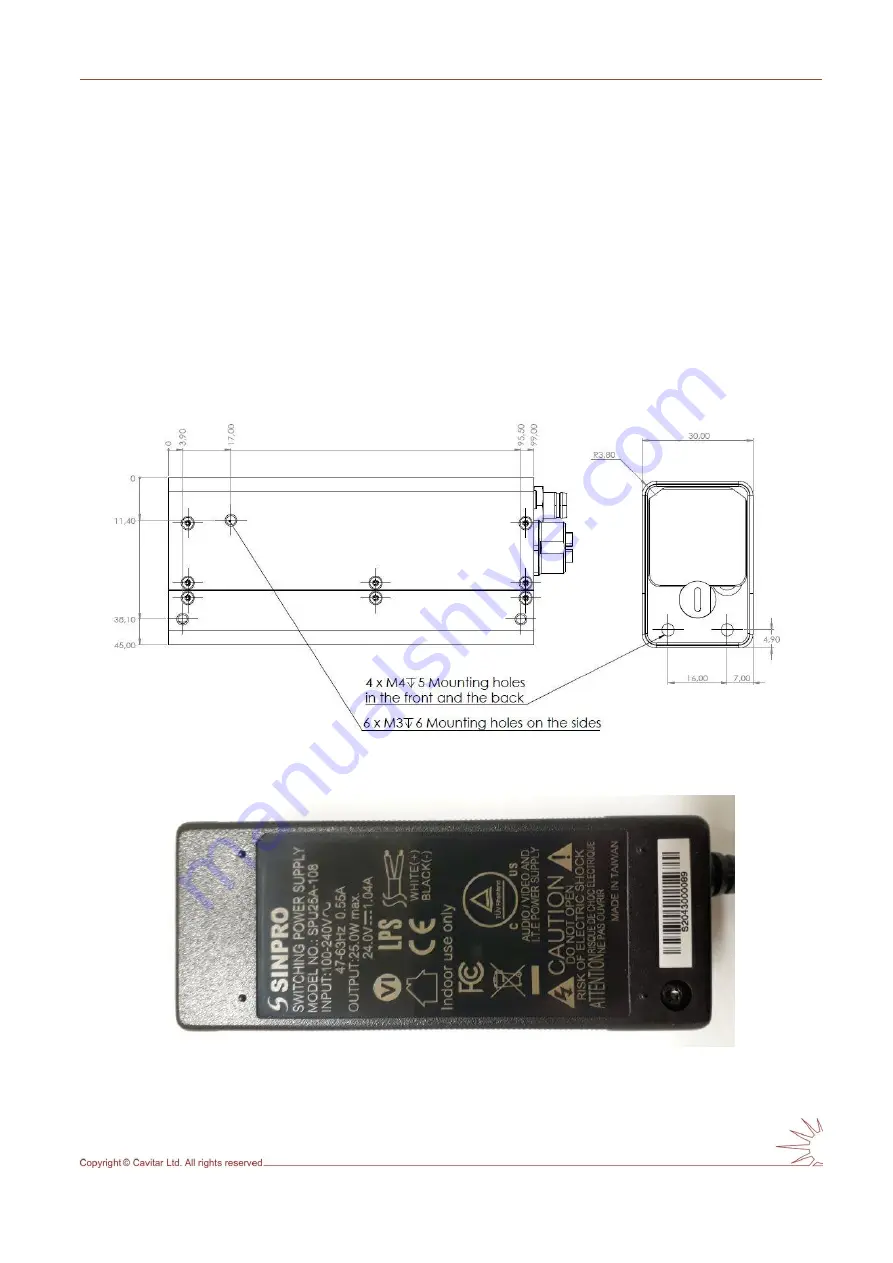
Fig. 3.5. Camera unit mechanical drawing.
Fig. 3.6. Bottom view of the power supply.
Содержание C300
Страница 1: ...CAVITAR Welding Camera C300 Operating Manual ...
Страница 14: ...12 Fig 4 2 close all other applications and click Next to start installation Fig 4 3 Click I Agree to continue ...
Страница 30: ...28 Fig 5 16 Guideline and grid properties ...
Страница 34: ...32 Fig 5 21 View after calibration ...