


16
The camera unit must be properly protected from excessive radiation, heat/cold, condensation,
vibration or mechanical forces (see Table 3.1 for more detailed specifications). If you feel
uncertain about the correctness of the installation and/or about the suitability of the
environment, please contact your vendor or Cavitar. Warranty does not cover damage caused
by improper installation.
Electrical connections
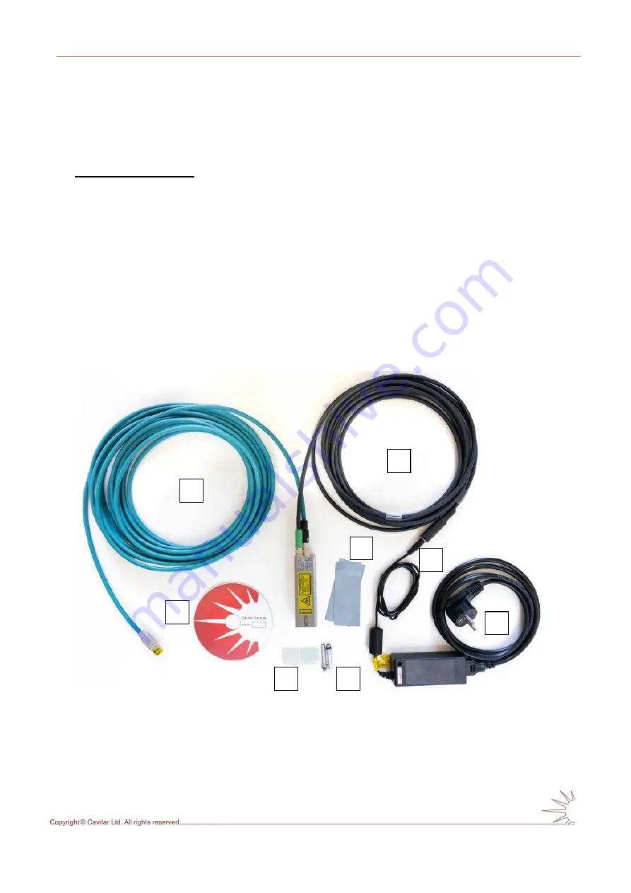
The electrical connections shall be made in the following way:
connect the power cable (see Fig. 4.9A) between camera unit (see Fig. 3.4H) and
power supply unit (see Fig. 4.9B)
connect the power supply cable (see Fig. 4.9C) to the power supply
connect the GigE cable (see Fig. 4.9D) between camera unit (see Fig. 3.4I) and
computer (computer is not included in the standard system)
ensure the camera unit housing is firmly connected to ground (see Fig. 3.4K)
Fig. 4.9 shows the welding camera system after the connections have been made. Also
installation CD (Fig. 4.9E), spare protective windows (Fig. 4.9F), cooling connectors for air
or liquid cooling (Fig. 4.9G) and thermally conductive sheets (Fig. 4.9H) are shown.
Fig. 4.9. Welding Camera system after the connections have been made.
A
B
D
C
G
F
E
H
Содержание C300
Страница 1: ...CAVITAR Welding Camera C300 Operating Manual ...
Страница 14: ...12 Fig 4 2 close all other applications and click Next to start installation Fig 4 3 Click I Agree to continue ...
Страница 30: ...28 Fig 5 16 Guideline and grid properties ...
Страница 34: ...32 Fig 5 21 View after calibration ...