


15
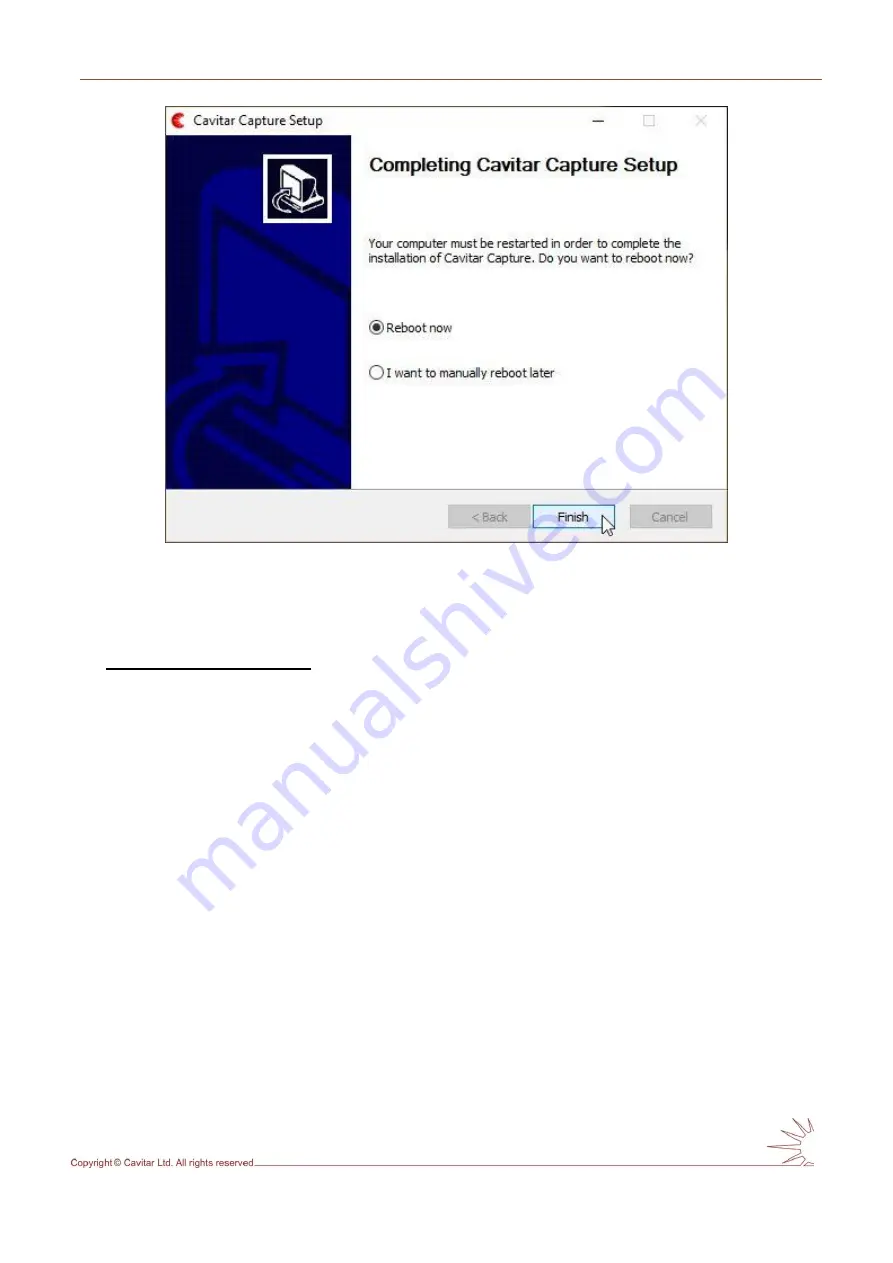
Fig. 4.8.
Select “Reboot now” and click “Finish”.
4.2 Hardware installation
Installation of camera unit
The camera unit should be mounted or clamped with an appropriate fixture in such a way that
the object is located at the working distance of the camera unit.
The mounting must enable
as efficient conductive
(low ambient temperature or heat load from process)
or active
(high
ambient temperature or heat load from process)
cooling of the camera unit as possible.
In case of conductive cooling, it is important to apply thermally conductive sheets between
the camera side(s) and the mounting as well as between the mounting and larger heat sink
(such as the body of machinery). It is also beneficial to maximize the area between camera
side(s) and mounting. The mounting should be made of material with high thermal
conductivity (such as aluminium).
If active cooling is applied, connect the cooling connectors (see Fig. 4.9G) to the threads of
the camera unit (see Fig. 3.4J, ensure the O-rings are in place; maximum torque 0,1 Nm) and
attach appropriate cooling system (air or liquid) to the connectors (suitable for hoses with
inner diameter of 6 mm). Only use cooling liquids and cooling equipment that can be in
contact with aluminium (electro-chemical corrosion must be prevented). The coolant must be
sufficiently warm (e.g. 20 ˚C) to avoid problems related to condensation. For more details, see
Table 3.1 and the notes related to it.
In order to minimize the effects of external electromagnetic fields, connect the chassis of
the camera to ground via the grounding threads (see Fig. 3.4K) or via an appropriate
mounting plate or heat sink.
Содержание C300
Страница 1: ...CAVITAR Welding Camera C300 Operating Manual ...
Страница 14: ...12 Fig 4 2 close all other applications and click Next to start installation Fig 4 3 Click I Agree to continue ...
Страница 30: ...28 Fig 5 16 Guideline and grid properties ...
Страница 34: ...32 Fig 5 21 View after calibration ...