79
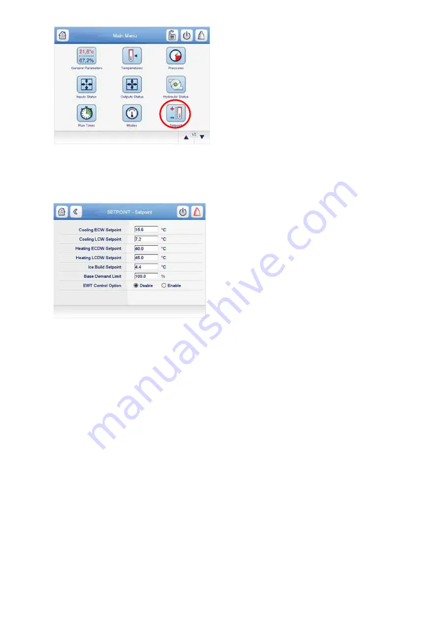
Fig 45: main menu
– setpoint table icon
The Setpoint screen is displayed (
see Fig. 46
). Set the base demand limit set point, and either the LCW set point
or the ECW set point. To set a value, press the appropriate set point, enter the value, and press OK. For more
information, see the PIC5+ Control User Manual.
Fig 46: Setpoint table screen
5.8.2 Input the local occupied schedule
Access the schedule screen and set up the occupied time schedule according
to the customer’s requirements. If
no schedule is available, the default is factory set for 24 hours occupied, 7 days per week including holidays. The
Schedule Menu as well as the Holiday Menu can be reached through the Configuration Menu. When the control
mode is LOCAL SCHEDULE, the chiller will be automatically started if the configured local schedule is occupied
and will be automatically shut down by the unoccupied schedule.
The Network Schedule should be configured if a CCN system is being installed. When control mode is
NETWORK, the chiller can be started and stopped by the CHIL_S_S software point as written by other equipment
through the network command and network schedule.
For more information about setting time schedules, please refer to the PIC5+ Control User Manual.
5.8.3 Input service configurations
For specific values or the following configurations, refer to the chiller performance data or job-specific data sheet:
• password
• log in/logout
• input time and date
• service parameters
• equipment configuration
• automated control test
PASSWORD
— The PIC 5+ control system provides different levels of access: Basic access, User access,
Advanced User/ Service access and Factory access. User access provides basic access to the chiller controls.
Advanced User access has access to all Service tables, and Factory user has access to factory tables. The PIC
5+ default password configurations are as follows:
• Basic User: No password required
• User: 1111
• Advanced User / Service Access: 2222
• Factory: 4444
Содержание PIC 5+
Страница 26: ...26 VFD not shown Fig 13 Sensors actuators location ...
Страница 52: ...52 Fig 24 19DV control box ...
Страница 53: ...53 1 Power supply 24V AC 2 LEN 3 CCN 4 Ethernet 5 USB Fig 25 19DV HMI box rear view ...
Страница 54: ...54 Fig 26 19DV IOB1 wiring Fig 27 19DV IOB2 wiring ...
Страница 57: ...57 ...
Страница 113: ...113 APPENDIX A SmartView SCREEN AND MENU STRUCTURE ...
Страница 114: ...114 Detailed menu description ...
Страница 116: ...116 APPENDIX B MAINTENANCE SUMMARY AND LOGSHEETS Cont 19DV monthly Maintenance Log ...