


11
Communication Cables
The communication transmission cables have the following
electrical characteristics:
• 2 signal conductors and one ground conductor of 20 AWG
or larger, 100% shielded
• One tinned copper braid (65% coverage)
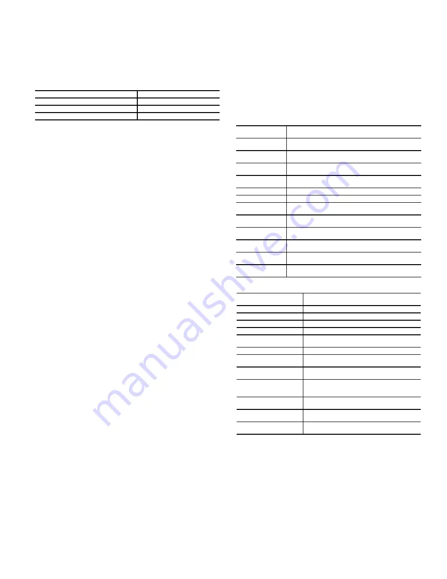
Recommended cables are shown below:
To avoid potential interference, route communication cables
between the starter and the chiller control panels as far away as
possible from high voltage cable and other likely disturbances.
Always separate communication cables from other cables and
always run wiring as directly as possible.
Sensors
PRESSURE TRANSDUCERS
Pressure transducers measure and control the pressures in the
unit. These electronic sensors deliver 0 to 5 VDC. The trans-
ducers can be calibrated through the controller. The pressure
transducers are connected to the IOBs. See Table 7.
TEMPERATURE SENSORS
The system uses electronic sensors to measure and control the
temperatures in the unit. There are three types of temperature
sensors: 5K thermistor, 10K thermistor, and RTD (resistance
temperature detector, 100 ohm, 3-wire) based on IOB channel
configurations. The temperature sensor range is –40°F (–40°C)
to 245°F (118°C). See Table 8.
Controls Outputs
EVAPORATOR/CONDENSER WATER PUMP
The controller regulates the evaporator/condenser water pump.
Note that Carrier requires full or parallel pump control.
INLET GUIDE VANE
The inlet guide vane adjusts the refrigerant vapor flow into the
compressor to adapt to change in the operating conditions of the
machine. To adjust the refrigerant flow, the guide vane opens or
closes to vary the cross-section of the refrigerant path. The high
degree of accuracy with which the guide vane is positioned en-
sures that the flow of refrigerant is precisely controlled.
ECONOMIZER ISOLATION VALVE (OPTION)
The economizer is an on/off valve that shuts off the economiz-
er gas vent line leading to the second stage of the compressor.
ECONOMIZER LIQUID BYPASS VALVE (OPTION)
The economizer liquid bypass valve is opened if lift difference
between condenser and evaporator is small. When the valve is
open liquid refrigerant can bypass the economizer and flow di-
rectly from the condenser to the evaporator and thereby avoid
the pressure loss associated with the economizer.
ENVELOPE CONTROL VALVE
The modulating Envelope Control valve artificially loads the
chiller and keeps it running under low load conditions or helps
to prevent surge conditions. Since this function can also reduce
the operating efficiency of the machine, this is a user-selectable
and configurable option.
VFD
The VFD modifies motor frequency to allow compressor start-up
and capacity control. The VFD controls continually monitor pa-
rameters to ensure compressor protection. If a problem occurs, the
controller triggers an alarm and the compressor is stopped.
FREE COOLING VALVE (OPTION)
The free cooling control allows the chiller to provide cooling
without running the compressor. The free cooling vent valve is
opened, allowing the refrigerant to bypass the compressor and
go straight from the evaporator to the condenser. This control
mode can only be used when the chiller is OFF and the external
air temperature is low enough to support this operation.
TOWER FAN HIGH/LOW
The controls provide optional fan tower control by a 24 VAC
output for tower fan low and another for tower fan high speed.
Table 7 — Pressure Transducers
Table 8 — Temperature Sensors
* Separate inputs used when the chiller is in network mode.
NOTE: Text in parentheses indicates applicable product.
USER INTERFACE
The PIC6 Human Machine Interface (HMI) is a color 10.4-in.
TFT touch screen. Navigation is either direct from the touch
screen interface or by connecting to a web interface at the
Ethernet IP port of the controller. The navigation menus are the
same for both connection methods.
Web Connection
Two web connections may be authorized at the same time. When
two users are connected simultaneously, there is no priority be-
tween users; that is, the last modification is in effect regardless
of the user. Connection is from a personal computer using a
USAGE
CABLE
Intra-Building
Belden 8772
High Temperature
Belden 85240
Plenum
Belden 89418
PRESSURE
TRANSDUCER
PURPOSE
Pump Input
Pressure
Measures the pressure at the input of the refrigerant
pump
Pump Output
Pressure
Measures the pressure at the output of the refrigerant
pump
Bearing Inlet
Pressure
Measures the pressure at the bearing inlet
Bearing Outlet
Pressure
Measures the pressure at the bearing outlet
Evaporator
Measures evaporator pressure
Condenser
Measures condenser pressure
Evaporator Water
Pressure Difference
(Optional) Measures pressure difference between entering
and leaving water.
Condenser Water
Pressure Difference
(Optional) Measures pressure difference between entering
and leaving water.
Evaporator Entering
Water
(Optional) Measures pressure of evaporator entering
water
Evaporator Leaving
Water
(Optional) Measures pressure of evaporator leaving water
Condenser Entering
Water
(Optional) Measures pressure of condenser entering
water
Condenser Leaving
Water
(Optional) Measures pressure of condenser leaving water
TEMPERATURE
SENSOR
PURPOSE
Entering Chilled Water
Measures entering evaporator water temperature
Leaving Chilled Water
Measures leaving evaporator water temperature
Entering Condenser Water
Measures entering condenser water temperature
Leaving Condenser Water
Measures leaving condenser water temperature
Evaporator Refrigerant
Liquid
Measures evaporator refrigerant liquid temperature
Compressor Discharge
Measures compressor discharge temperature
1st Stage Bearing
Measures the temperature of the bearings in the
first stage of the compressor
2nd Stage Bearing
Measures the temperature of the bearings in the
second stage of the compressor
Bearing Refrigerant Supply
(available for older software
only)
Measures the temperature of the refrigerant sup-
ply for the bearings
Chilled Water Supply
(Optional)*
Measures the temperature of the chilled water
supply
Chilled Water Return
(Optional)*
Measures the temperature of the chilled water
return
Motor Winding
Measures the temperature of each phase of the
compressor motor
Содержание AquaEdge 19DV series
Страница 6: ...6 Fig 3 IOB2 and IOB3 AVAILABLE FOR OLDER SOFTWARE...
Страница 7: ...7 Fig 4 IOB 4...
Страница 8: ...8 Fig 5 19DV Control Panel Abbreviations...
Страница 9: ...9 Fig 6 19DV Control Wiring...


