


17
ENG
μc0300053EN rel. 2.2 - 14.12.2021
Installation
2.8 Electrical
installation
Important:
When laying the wiring, “physically” separate the power part from the control part. The proximity of these two
sets of wires will, in most cases, cause problems of induced disturbance or, over time, malfunctions or damage to the compo-
nents. The ideal solution is to house these two circuits in two separate cabinets. Sometimes this is not possible, and therefore the
power part and the control part must be installed in two separate areas inside the same panel.
For the control signals, it is recommended to use shielded cables with twisted wires. If the control cables have to cross over the
power cables, the intersections must be as near as possible to 90 degrees, always avoiding running the control cables parallel
to the power cables.
Pay attention to the following warnings:
• use cable ends suitable for the corresponding terminals. Loosen each screw and insert the cable ends, then tighten the
screws. When the operation is completed, slightly tug the cables to check they are suffi
ciently tight;
• separate as much as possible the probe signal, digital input and serial line cables from the cables carrying inductive loads
and power cables to avoid possible electromagnetic disturbance. Never run power cables (including the electrical cables) and
probe signal cables in the same conduits. Do not install the probe cables in the immediate vicinity of power devices (contac-
tors, circuit breakers or similar);
• reduce the path of the probe cables as much as possible, and avoid spiral paths that enclose power devices;
• avoid touching or nearly touching the electronic components fi tted on the boards to avoid electrostatic discharges (ex-
tremely damaging) from the operator to the components;
• do not secure the cables to the terminals by pressing the screwdriver with excessive force, to avoid damaging the controller:
maximum tightening torque 0.22-0.25 N•m;
• for applications subject to considerable vibrations (1.5 mm pk- pk 10/55 Hz), secure the cables connected to the controller
around 3 cm from the connectors using clamps;
• all the extra low voltage connections (analogue and digital inputs, analogue outputs, serial bus connections, power supplies)
must have reinforced or double insulation from the mains network.
2.9
C
onnecting serial ports with two circuits
For serial connections (FBus and BMS ports), the cables used must be suitable for the RS485 standard (shielded twisted pair,
see the specifi cations in the following table). The earth connection of the shield must be made using the shortest connection
possible on the metal plate at the bottom of the electrical panel.
Master device
S
erial port
Lmax (m)
Wire/wire capaci-
tance (pF/m)
Resistance on fi rst and
last device
Max no. of slave
devices on bus
Data rate
(bit/s)
μChiller
FBus 10
<90
120
Ω
16
19200
PC (supervision)
BMS
500
<90
120 Ω
16
115200
Notice:
120 Ω 1/4W terminating resistors on the fi rst and last devices in the network must be used when the length exceeds
100 m.
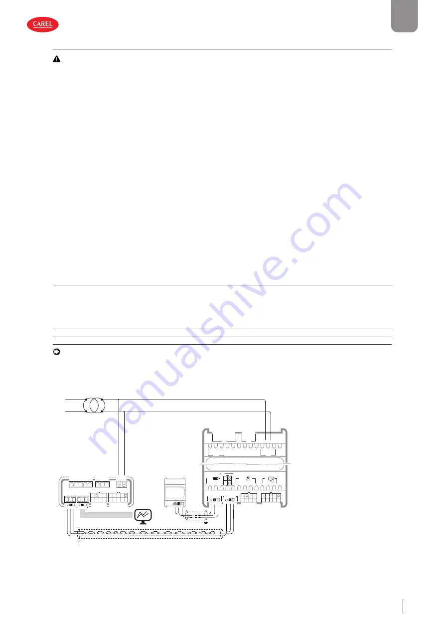
For two-circuit units, the power supply connections must be in phase between the two controllers (G0 on the master controller
and G0 on the slave controller connected to the same power supply wire); the serial connection between the two controllers (J5
FBus on the master and J4 BMS on the slave) must be made as shown in the fi gure (+ with + and - with -).
G0 G
C
C
NO1
NO2
NO3
NO4
NO5
J2
J3
S1 S3 5V
S2
Y2
Y1
ID1
ID2
ID3
ID5
ID4
S4
S6 +V
VL
S5
J4 BMS
J5 FBus
J4 BMS
J3
J2
J5 FBus
S1 S3 5V
S2
Y2
Y1
ID1
ID2
ID3
ID5
ID4
S4
S6 +V
VL
S5
J1
J7
G0 G
J6
C
C
NO1
NO2
NO3
NO4
NO5
J8
J10
J14
J9
S7
ID6
J11
C
NO6
Master
Slave
shield
EVD evolution
twin
shield
L
N
Fig. 2.o
Содержание uChiller UCHBD00001230
Страница 2: ......
Страница 4: ......
Страница 6: ......
Страница 105: ...105 ENG chiller 0300053EN rel 2 2 14 12 2021 Release notes Notes...
Страница 106: ...106 ENG chiller 0300053EN rel 2 2 14 12 2021 Notes...
Страница 107: ......


