


ENG
“FLSTDMAHUE” +030220961 - rel. 1.1 - 28.08.2019
27
4.
A file is selected by pressing Enter when the cursor is positioned on the
file name. A selected file is identified by the “*” symbol on the left;
48?61 PENP$0
#*04?1#*/
'-*61
'-45%.*61
5.
Once having selected the files (all in the same directory), start the upload
procedure by pressing PRG; at the end, a message will be shown on the
display prompting to remove the pen drive, wait and then switch the
controller on/off to complete installation.
6PLOADCOMPLETE
REMOVE64BKEY
ANDWAITRESET
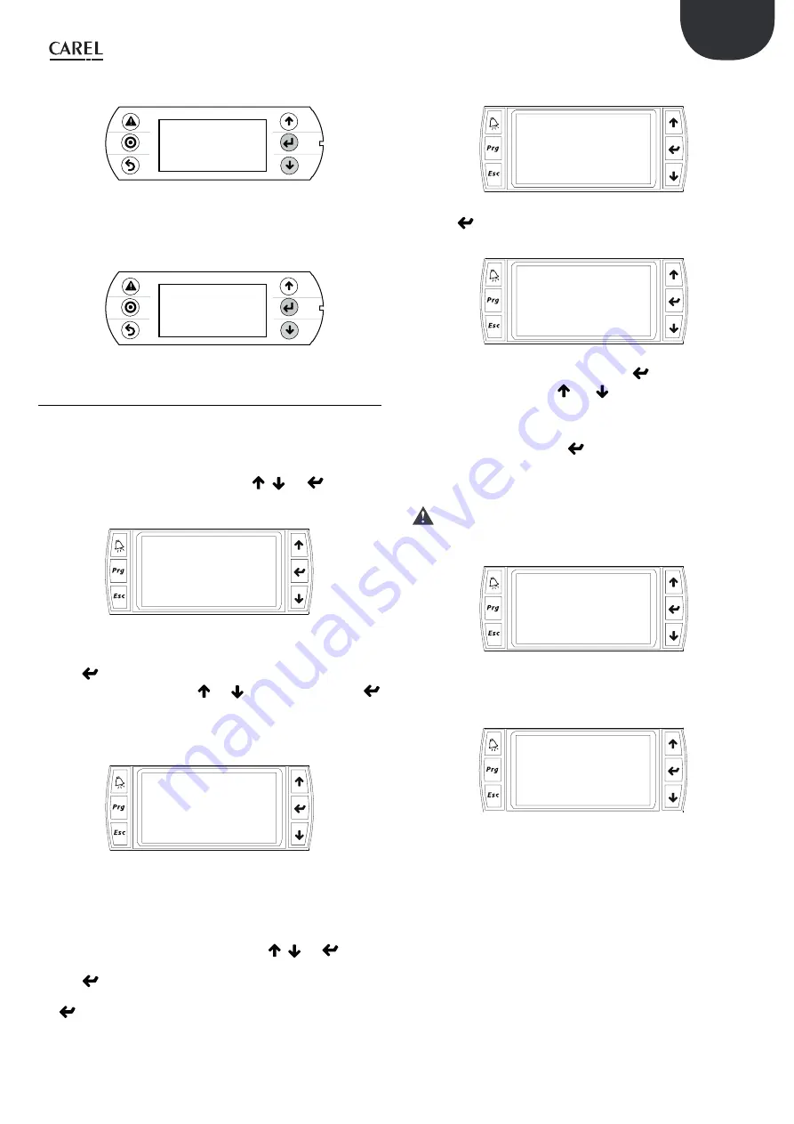
6.4 Setting the terminal address
The address of the terminal can be set in the range from 0 to 32; addresses
between 1 and 32 are used by the pLAN protocol, while address 0 identifies
the Local terminal protocol, used for non-graphic point-to-point connections
and to configure the pCO controller. The default address is 32. The address of
the terminal can only be set after having powered the terminal via the RJ12
connector. To access configuration mode press
,
and
together for
at least 5 seconds; the terminal will display a screen similar to the one shown
below, with the cursor flashing in the top left corner::
Display address
setting........:32
I/O Board address:01
To modify the address of the terminal (“Display address setting”) carry out the
following operations in sequence.
1.
Press
once: the cursor will move to the “Display address setting” field;
2.
Select the desired value using
nd
, and confirm by pressing
again;
3.
If the value selected is different from the value saved, the following screen
will be displayed and the new value will be saved to the permanent
memory on the display.
Display address
changed
If the address field is set to 0, the terminal communicates with the pCO board
using the Local terminal protocol and the “I/O Board address” field disappears,
as it no longer has any meaning. To modify the list of the terminals (private
and shared) associated with a pCO board, carry out the following operations
in sequence:
4.
Enter configuration mode (see above) pressing
,
and
together
for at least 5 seconds.
5.
Press
twice: the cursor will move to the “I/O Board address” field.
6.
Select the address of the pCO board in question and confirm by pressing
.
.
Then the pCO controller will start the configuration procedure, opening a
screen similar to the following.
Terminal config
Press ENTER
to continue
7.
Press
again: the configuration screen will be shown, similar to the
one below.
P:01 Adr
Priv/Shared
Trm1 32 Sh
Trm2 02 Pr
Trm3 -- --
8.
Configure the terminals as desired. Pressing.
moves the cursor from
one field to the next, while
and
change the value of the current
field. P:xx represents the address of the selected pCO board (in the
example in the figure, this is board 1).
9.
To exit the configuration procedure and save the data, select “Ok?”, set
“Yes” and confirm by pressing
. During the configuration procedure,
if the terminal remains inactive (no button is pressed) for more than 30
seconds, the pCO board automatically interrupts the procedure without
saving any changes.
Important
: if during operation the terminal detects inactivity on the
pCO board it is connected to, the display is cancelled and a message similar
to the one shown below is displayed.
I/O board fault
If the terminal detects inactivity of the entire pLAN network, that is, it does
not receive any messages from the network for 10 seconds consecutively, the
display is cancelled completely and the following message is shown:
NO LINK
Содержание FLSTDMAHUE
Страница 2: ......
Страница 4: ......
Страница 91: ...ENG FLSTDMAHUE 030220961 rel 1 1 28 08 2019 91 ...
Страница 92: ...ENG FLSTDMAHUE 030220961 rel 1 1 28 08 2019 92 ...
Страница 93: ......


