Carel EVD ice Скачать руководство пользователя страница 18

18

ENG

“EVD ice” +0300038EN - rel. 1.1 - 23.04.2018

Par.

Description

Def.

Min.

Max.

UoM

Type Carel Modbus® R/W Note

Si

Unit of  measure 1=°C/K/barg ¦ 2=°F/psig

1

1

2

-

I

16

143

R/W

IA

Enable operating mode modification  0/1 = yes/ no

0

0

1

-

I

15

142

R/W

U1

Enable manual valve positioning  0/1 = no/ yes

0

0

1

-

D

11

10

R/W

U2

Manual valve position

0

0

999

step

I

7

134

R/W

U3

Valve control steps: 1/2 = 480/960 steps

1

1

2

-

I

11

138

R/W

U4

Valve opening at start-up (evaporator/valve capacity ratio)

50

0

100

%

I

19

146

R/W

Fr

Firmware release

-

-

-

-

A

9

8

R

di

DI configuration: 1=start/stop regulation; 2=backup regulation

1

1

2

-

I

18

145

R/W

rt

Reserved

1

1

1

-

L1

S1 alarm: Minimum pressure

-1

-85(-121)

S1 alarm:  

Max pressure

barg (psig)

A

20

19

R/W

H1

S1 alarm: Maximum pressure

-

S1 alarm:  

Min press.

200 (392) barg (psig)

A

21

20

R/W

Tab. 7.a 

8.  NETWORK CONNECTION

The driver can be connected via a network connection to:

1. 

a  computer running the VPM software, for setting the parameters 
before commissioning;

2. 

a pCO controller, loaded with the application program;

3. 

a  PlantVisor/PlantVisorPRO supervisor, for remote monitoring and 
alarm detection.

8.1  RS485 serial configuration

n1 assigns to the controller an address for serial connection to a 
supervisory and/or telemaintenance system.

Par. Description

Def.

Min.

Max. UoM

n1 Network address

1

1

99

-

n2 Baud rate (bit/s)

0    4800,   2 stop bit,   parity none

1

  9600,   2 stop bit,   parity none

2

19200,   2 stop bit,   parity none

3

  4800,   1 stop bit,   parity none

4

  9600,   1 stop bit,   parity none

5

19200,   1 stop bit,   parity none

6

  4800,   2 stop bit,   parity even

7

  9600,   2 stop bit,   parity even

8

19200,   2 stop bit,   parity even

9

  4800,   1 stop bit,   parity even

10   9600,   1 stop bit,   parity even

11 19200,   1 stop bit,   parity even

12   4800,   2 stop bit,   parity odd

13   9600,   2 stop bit,   parity odd

14 19200,   2 stop bit,   parity odd

15   4800,   1 stop bit,   parity odd

16   9600,   1 stop bit,   parity odd

17 19200,   1 stop bit,   parity odd

2

0

17

-


Important: 

all controllers connected in a serial network need to be 

set with the same communication parameters.

8.2  Network  connection for commissioning 

via PC

 Warnings:

• 

fasten the converter properly so as to prevent disconnection;

• 

complete the wiring without power connected;

• 

keep the CVSTDUMOR0 interface cables separate from the power 
cables (power supply);

• 

in compliance with standards on electromagnetic compatibility, a 
shielded cable suitable for RS485 data transmission is used.

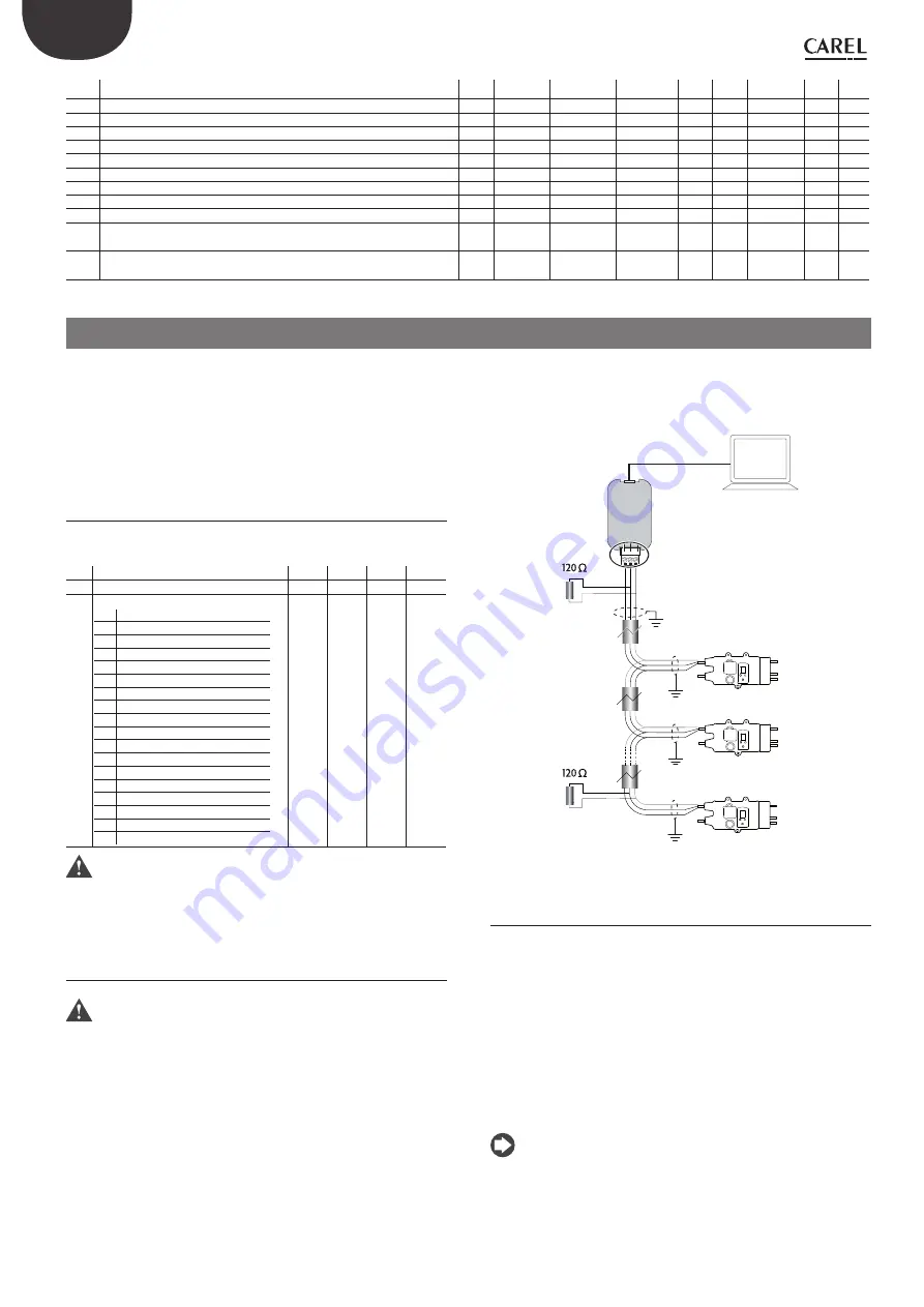
The RS485 converter is used to connect a computer running the VPM 
software to the EVD ice driver via a serial network, for commissioning the 
controllers. The system allows a maximum of 99 units, with a maximum 
network length of 500 m. Connection requires the standard accessories 
(RS485-USB converter, CAREL P/N CVSTDUMOR0) and a 120 Ω terminating 
resistor to be installed on the terminals of the last connected controller. 

Connect the RS485 converter to controllers and make the connections 
as shown in the figure. To assign the serial address, see parameter n1. See 
the converter technical leaflets for further information.

GND

USB-485

Converter

CVSTDUMOR0

USB

T+ T -

shield

shield

shield

shield

*

*

EVD ice 1

EVD ice 2

EVD ice ...n

VPM

Fig. 8.a

8.3  Visual parameter manager

Go to http://ksa.carel.com and follow the instructions below. Select in 
sequence:

1. 

 “Software & Support”

2. 

“Configuration & Updating Softwares”

3. 

 “Parametric Controller Software”

4. 

“Visual Parametric Manager”

A window will open with the possibility to download two files:

1. 

VPM_setup_X.Y.Z.W_full.zip: complete program;

2. 

X.Y.Z.W_VPM_Devices_Upgrade.zip: upgrade for supported devices;

If this is the first installation, select Setup full, otherwise Upgrade. The 
program installs automatically by running setup.exe.

Note:

 if choosing complete installation (Setup full), uninstall any 

previous versions of  VPM.

Содержание EVD ice

Страница 1: ...H i g h E f f i c i e n c y S o l u t i o n s EVD ice NO POWER SIGNAL CABLES TOGETHER READ CAREFULLY IN THE TEXT User manual Superheat control for unipolar electronic expansion valve...

Страница 2: ......

Страница 3: ...not use corrosive chemicals solvents or aggressive detergents to clean the device do not use the product for applications other than those specified in the technical manual All of the above suggestio...

Страница 4: ......

Страница 5: ...2 Special control function smooth lines 14 5 3 Service parameters 14 6 PROTECTORS 15 6 1 Protectors 15 7 PARAMETERS TABLE 17 8 NETWORK CONNECTION 18 8 1 RS485 serial configuration 18 8 2 Network conne...

Страница 6: ......

Страница 7: ...om controllers 1 1 Models P N Description EVDM011R3 EVD ice 115 230 V E2V stator display EVDM011R1 EVD ice 115 230 V E2V stator display Ultracap module connector EVDM011R4 EVD ice 115 230 V E3V stator...

Страница 8: ...portant install EVD ice on the evaporator away from the places where ice forms connect the power and serial cables in the IP65 junction box for assembly of the E2V E3V valve see the ExV system guide 0...

Страница 9: ...Regulator P T EEV M Condenser Electrical panel Compressor Condenser unit Evaporator unit Solenoid valve IP65 L N Fig 2 d WITHOUT SOLENOID VALVE WITH ULTRACAP MODULE COLD ROOM IN COLD ROOM OUT COLD RO...

Страница 10: ...d pressure probe see the chapter on Commissioning 2 connectthepowercableandthedigitalinputcable forthemaximum length see the technical specifications 3 poweronthedriver thedisplaywilllightup andthedri...

Страница 11: ...than 9 are displayed in two steps first the sign then the tens and units GASType Mode Super Heat GASType Mode Super Heat 123 GASType Mode Super Heat GASType Mode Super Heat 99 Fig 3 b Note the decima...

Страница 12: ...Superheat set point GASType Mode Super Heat 7 Press PRG Set for 2 seconds to exit the commissioning procedure and start control The standard display is shown 4 2 Parameters first configuration Import...

Страница 13: ...through the nozzle corresponds to the flow rate required by the compressor In this way the evaporation process will take place along the entire length of the evaporator and there will be no liquid at...

Страница 14: ...ol temperature approaches the set point the Smooth_line parameter is used to prevent the valve from closing by reducing the evaporator s cooling capacity In order to use this function the digital inpu...

Страница 15: ...activation threshold depending on the operating conditions of the controlled unit this is set in Service programming mode integration time which determines the intensity if set to 0 the protector is...

Страница 16: ...refrigerant charge or when there are sudden variations in the load The protector is also useful in multiplexed systems showcases as allows all the utilities to be enabled at the same time without cau...

Страница 17: ...Po Valve opening 0 100 A 1 0 R CP PID proportional gain 15 0 800 A 11 10 R W ti PID integral time 150 0 999 s I 17 144 R W C1 LowSH protection threshold 5 9 5 9 Superheat set point K F A 12 11 R W C2...

Страница 18: ...00 2 stop bit parity odd 15 4800 1 stop bit parity odd 16 9600 1 stop bit parity odd 17 19200 1 stop bit parity odd 2 0 17 Important all controllers connected in a serial network need to be set with t...

Страница 19: ...RS485 rear connector Offline Device model Online Offline Device setup Read instant values of control parameters Select Load to load a list of project parameters hex modify and save a new project Setup...

Страница 20: ...iguration page parameters p_GAS_TYPE refrigerant and p_SUPER_MAIN_REGULATION type of control b on the Configuration page parameter p_SH_SET Fig 8 m 3 Savethelistofparameterswithanewname forexample NEW...

Страница 21: ...om dew_f_l Dew f low 17239 32768 32767 I 35 162 R W Net_alarm Network alarm 0 0 1 D 1 0 R all E6 Emergency_closing_alarm Mains power failure 0 0 1 D 2 1 R all E5 S1_alarm Probe S1 alarm 0 0 1 D 3 2 R...

Страница 22: ...r or when reaching the control set point It can also occur when opening the digital input which involves closing the valve or in the event of a probe alarm In general it can be said that the electroni...

Страница 23: ...a power failure proceed as follows remove the valve stator set the PID proportional gain 0 The valve will remain stopped at the initial opening position set by corresponding parameter Retrieve physica...

Страница 24: ...ent of probe or valve malfunctions to protect the compressor using the relay to control the solenoid valve or to simply signal a possible risk In fact incorrect measurement of the evaporation pressure...

Страница 25: ...inets only Decrease the value of the Valve opening at start up parameter on all the utilities making sure that there are no repercussions on the control temperature Liquid returns to the compressor on...

Страница 26: ...the valve by placing it in manual control and closing or opening it com pletely One complete opening must bring a decrease in the superheat and vice versa If the movement is reversed check the electri...

Страница 27: ......

Страница 28: ...EL INDUSTRIES HeadQuarters Via dell Industria 11 35020 Brugine Padova Italy Tel 39 049 9716611 Fax 39 049 9716600 e mail carel carel com www carel com Agenzia Agency EVD ice 0300038EN rel 1 1 23 04 20...

Отзывы: