


14
ENG
“EVD ice” +0300038EN - rel. 1.1 - 23.04.2018
PID parameters
Superheat control uses a PID algorithm. The control output is calculated
as the sum of separate contributions: proportional and integral.
•
the proportional action opens or closes the valve proportionally to
the variation in the superheat temperature. Thus the greater the K
(proportional gain)
the higher the response speed of the valve. The
proportional action does not consider the superheat set point, but
rather only reacts to variations. Therefore if the superheat value does
not vary significantly, the valve will essentially remain stationary and
the set point cannot be reached;
•
the integral action is linked to time and moves the valve in proportion
to the deviation of the superheat value from the set point. The greater
the deviations, the more intense the integral action; in addition, the
lower the value of Ti (
integral time)
, the more intense the action
will be. The integral time, in summary, represents the intensity of the
reaction of the valve, especially when the superheat value is not near
the set point.
See the “EEV system guide” +030220810 for further information on
calibrating PID control.
Par. Description
Def.
Min.
Max.
UoM
-
Superheat set point
11(20) LowSH: threshold 55 (99) K(°F)
CP PID proport. gain
15
0
800
-
ti
PID integral time
150
0
999
s
Note:
when selecting the type of Mode, the PID control values
suggested by CAREL will be automatically set for each application.
Protector control parameters
See the chapter “Protectors”.
5.2 Special control function: smooth lines
Note:
the Smooth_line parameter is only accessible via the
supervisor.
The smooth lines function optimises evaporator capacity based on actual
cooling demand, allowing more effective and stable control. The function
completely eliminates traditional on/off control cycles, modulating
the temperature exclusively using the electronic valve; superheat set
point is controlled through a precise PI control algorithm based on
the actual control temperature. The master controller (connected via
serial to EVD mini), through dynamic management of the Smooth_line
parameter, modifies the superheat set point for management of the
electronic expansion valve, from a minimum (SH_SET) to a maximum
( Smooth_line): this consequently acts directly on the PID
control algorithm that modifies the valve position. This is useful when
the control temperature approaches the set point; the Smooth_line
parameter is used to prevent the valve from closing, by reducing the
evaporator’s cooling capacity. In order to use this function, the digital
input must be configured as BACKUP. The Smooth_line parameter thus
allows the control set point to be adjusted instantly. In the event where
there is no network connection, the Smooth_line parameter is reset so as
to resume normal control (START/STOP from digital input and SH_SET as
the superheat set point). The main effects are:
•
no swings in temperature and superheat due to the set point being
reached;
•
stable temperature and superheat control;
•
maximum energy savings due to load stabilisation.
Par.
Description
Def.
Min.
Max. U.M.
di
DI configuration
1=start/stop
2=control backup
1
1
2
-
Smooth_line A: superheat set point
offset for smooth lines
0
-99(-55)
99(55) K/°F
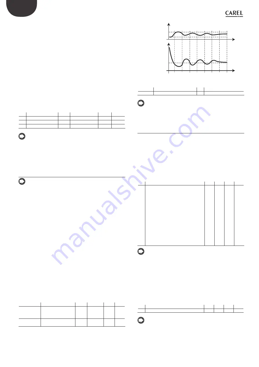
t
Temp. set
SH set
Smooth_line
t
Fig. 5.b
Key
SH set
Superheat set point
t
time
Temp.set Temperature set point
Note:
the temperature setting based on the corresponding set
point is managed by the master controller, while superheat control is
managed by the EVD ice.
5.3 Service parameters
The other configuration parameters, to be set where necessary before
starting the controller, concern :
•
the type of ratiometric pressure probe;
•
the serial address for network connection;
•
the type of unit of measure;
•
enabling change in type of control (Mode);
•
the number of steps (480/960) to control valve position.
Type of pressure probe (par. S1)
S1 is used to select the type of ratiometric pressure probe.
Par. Description
Def. Min. Max. UoM
S1
type of probe S1
1 = -1…4.2 barg
2 = 0.4…9.3 barg
3 = -1…9.3 barg
4 = 0…17.3 barg
5 = 0.85…34.2 barg
6 = 0…34.5 barg
7 = 0…45 barg
8 = -1…12.8 barg
9 = 0…20.7 barg
10 = 1.86…43.0 barg
11 = Reserved
12 = 0...60 barg
13 = 0...90 barg
3
1
13
-
Note:
when setting the probe type, the maximum and minimum
limits for the pressure alarm are automatically defined. See “Variables
aaccessible via serial connection”.
Network address (par. n1)
See the “Network connection” chapter.
Unit of measure (par. Si)
It is possible to select the measure system of the driver:
•
international (°C, K, barg);
•
imperial (°F, psig).
Par. Description
Def. Min. Max. UoM
Si
Unit of measure: 1=°C/K/barg; 2=°F/psig 1
1
2
-
Note:
the unit of measure K relates to degrees Kelvin adopted for
measuring the superheat and the related parameters.
When changing the unit of measure, all the values of the parameters
saved on the driver and all the measurements read by the probes will
be recalculated. This means that when changing the units of measure,
control remains unaltered.