_________________________________________________________________________________________________________________________
Card Access Sensor Bridge
Page 3 of 12
Quick Start & Installation Guide
Card Access, Inc.
Card Access Sensor Bridge
Quick Start and Installation Guide
Enable seamless use of GE sensors in the Control4
®-
automated home
Welcome and congratulations on your purchase of the Card Access Sensor Bridge. This Quick Start & Installation Guide
is an overview of configuring your Sensor Bridge with a Control4 System. This guide assumes that you are a qualified and
trained Control4 dealer.
Introduction
The Card Access Sensor Bridge is a device capable of receiving and interpreting signals from GE/ITI sensors and
integrating these signals with a Control4 System via the Control4 ZigBee wireless mesh. This device gives the
homeowner the ability to utilize the wide range of GE sensors available as accessories to the Control4 system.
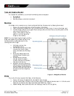
The device consists of a self-contained, wall-mountable bridge in a plastic enclosure. It is powered by a 12V DC
adapter.
Specifications
ZGB10A Specifications
Dimensions
4.6” x 14.4” x 1.5” (117mm x 366mm x 38mm)
Weight
0.5 Lbs (0.23Kg)
Maximum Ambient Operational
Temperature
140°F (60°C)
Power Input
12VDC, 100mA
Operational Environment
Type 1 Device shall be mounted in a dry, moisture-protected location.
Site Requirements and Wiring Options
•
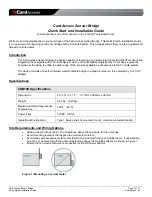
Allow at least 9 inches (22.9 cm) of clearance above the enclosure for the antennas.
•
Avoid mounting locations that expose the module to moisture.
•
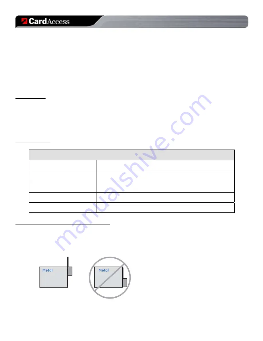
Avoid areas with excessive metal or electrical wiring including furnace and utility rooms. If unavoidable,
mount on or near metal with the antenna extending above the metallic surfaces as shown in
Figure 1
.
•
Ensure that an electrical source is accessible for the DC power adaptor.
Figure 1 - Mounting on or near metal


