background image


Page 

4

 of 

35


3.1.1 

EQUIPMENT STARTUP PROCEDURE   


A.  The pump and all lines shall be clean and free from any contamination.   

B.  Turn off air to main pump. Be sure all pressure is removed from lines.  

Prior to loading heated material under follower plates, premix Parts A and B for 2 –  3 
minutes.  

Load heated material under follower plates.  Lower follower plates on to buckets and 
bleed off trapped air and then close bleed valves. 

NOTE:  If using pump with holding tanks, use transfer pumps and begin filling unit with 
material. 

Turn on the main pump air to assist in the movement of material into the material lines.  
Continue pumping Part A and Part B until a steady flow of material is present at the end 
of each fluid delivery hose.  Turn off all air. 

C.   Turn on fluid and line heaters, and adjust temperature of the heaters to 140-

160˚F (60˚C 

71˚C).  Wait  at  least  30  minutes  for  material  to  heat  thoroughly  or  recirculate  the 

material until the temperature of the material reaches the temperatures stated above. 

D.   The pump shall be set for a 1:1 ratio and it is important to check this ratio before 

beginning any work.  


Hose Bundle: ¾” (100’ maximum)              Whip Hose: ½” (20’ maximum). 

E.   The air pressures needed for properly delivering material may vary from pump to pump, 

and adjustments may vary from the stated pressures herein. 

F.  The use of other plural component equipment (with holding tanks), shall be approved by 

CARBOLINE prior to use. 

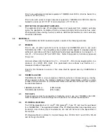
With the air still turned off to the main pump,  

Adjust  the air pressure to the "A" component transfer pump to 40 psi. Adjust the air 
pressure to the "B" component transfer pump to 40 psi.  While directing the discharge 
into separate, clean and equally sized containers, turn the air on to the main pump. 
Keep pumping until both or one of the containers is full.  Insure that the transfer pumps 
are not continuously cycling.  If this is so, turn up the main pump to increase the back 
pressure or reduce the pressure on the transfer pumps (see note below). 

G.   If containers contain equal volumes, the 1:1 ratio has been achieved. If not, check for 

restrictions in the air or material flow  and material temperature. Repeat above 
procedure. If ratio is still not correct, inspect equipment and pump packings and replace 
if needed.  Repeat the above procedure until a 1:1 ratio is achieved.  


CARBOLINE  requires  that when using plural component pumps, which have 
holding tanks and recirculation capabilities, the material shall not be recirculated 
more than one time, and the temperature of the holding tanks shall not exceed 
140

˚

F


(60

˚C).  Tank mixers should be used at minimum revolutions. 


Material shall be pre-heated to a minimum of 100

˚

F (37.8

˚

C) prior to introduction to 

the pumping units. Thoroughly mix Parts A and B well - separately - before using.   


Содержание Thermo-Lag 3000

Страница 1: ...THERMO LAG 3000 Fire Barrier System Application Manual Commercial Light Industrial Market ASTM E119 UL 263 NFPA 251 January 2016 Rev 4...

Страница 2: ...S ACCURATE AND COMPLETE TO THE BEST OF OUR KNOWLEDGE AS OF THE DATE PRINTED THE INFORMATION IN THIS DOCUMENT IS SUBJECT TO CHANGE WITHOUT NOTICE CARBOLINE MAKES NO WARRANTY EXPRESSED OR IMPLIED OF ANY...

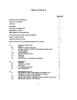
Страница 3: ...TROL MANUAL 1 1 2 1 QUALIFICATIONS OF APPLICATORS RESPONSIBILITIES OF PERSONNEL 1 1 2 2 REQUIREMENTS 1 1 3 SAFETY PRECAUTIONS 1 1 4 DELIVERY 1 1 5 STORAGE 1 1 6 PROTECTION OF ADJACENT SURFACES 2 2 0 M...

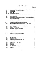
Страница 4: ...ION PROCEDURES 8 5 1 INSTALLATION OF MESH ON STRUCTURAL STEEL I AND H SECTIONS 9 5 2 FINAL THERMO LAG 3000 APPLICATION 10 5 2 1 TERMINATION ONTO NON FIREPROOFED STEEL 10 5 3 FINAL THICKNESS 10 5 4 SAM...

Страница 5: ...h Details for ASTM E119 Certification UL Design No N608 Restrained and Unrestrained Beam Ratings ANSI UL263 Intertek Design No CC CA 180 02 Column ASTM E119 09c Intertek Design No CC BA 180 01 Restrai...

Страница 6: ...subsections have a numerical designation For example 2 3 1 represents Chapter 2 Section 3 Subsection 1 Illustrations and drawings generally appear at the end of this document Breakdown of Information...

Страница 7: ...lation Procedures in This Guide The installation steps and procedures in this guide were prepared with the best available data All of the steps and procedures presented in this guide are based upon te...

Страница 8: ...and recognize their statutory obligations with regard to health and Safety 1 3 SAFETY PRECAUTIONS The Applicator shall follow standard industrial hygiene practices for the handling of chemical coating...

Страница 9: ...er List All steel surfaces shall be blasted to a 1 5 2 0 mils 37 50 microns angular profile to a minimum of a SSPC SP6 Sa2 For galvanized steel surfaces see Section 4 3 Galvanized Surface Preparation...

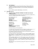
Страница 10: ...713 923 2771 Commack NY 11725 MODEL NO 631 462 2952 397 884 SQ GRACO H D Fixed Ratio Tank Mounted Pump We recommend the use of tank mounted pumps It is essential that all the equipment used by the App...

Страница 11: ...from the stated pressures herein F The use of other plural component equipment with holding tanks shall be approved by CARBOLINE prior to use With the air still turned off to the main pump Adjust the...

Страница 12: ...45 Graco Heavy duty RAC non diffuser tips Fan Size 6 10 Material Hose Solvent Resistant 3 4 I D 50 Max 1 2 I D Whip hose 25 Max Pressure at Gun 2500 3000 psi Air Requirements 40 100 cfm 100 psi per un...

Страница 13: ...5 2 0 mils 37 50 microns to a minimum of a SSPC SP6 Sa 2 4 1 3 PRIMING Only primer systems acceptable by CARBOLINE shall be used under THERMO LAG 3000 The primer shall be applied in accordance with th...

Страница 14: ...ns Prime with Carboguard 893 SG Primer 3 5 mils 75 125 microns DFT per SSPC PA2 4 4 STAINLESS STEEL SURFACE PREPARATION All steel surfaces shall be blasted to a SSPC SP7 Sa 1 with a minimum angular an...

Страница 15: ...the weight of subsequent coats The thickness which can be applied in a single coat will depend on the temperature humidity applicator technique etc The time between coats is largely dependent upon am...

Страница 16: ...er can be used to improve the surface quality Please read the THERMO LAG 3000 product data sheet before application commences Excessive build up of THERMO LAG 3000 in angle areas can be removed or lev...

Страница 17: ...ne point shall not be less than 80 of the specified thickness The overall average thickness must be equal to or greater than the specified thickness The number of thickness checks and other issues reg...

Страница 18: ...strate with a disc saw around the area to be removed Make sure that the steel substrate is not damaged A power chisel can then be used to chip away the THERMO LAG 3000 from the substrate It is essenti...

Страница 19: ...ods The THERMO LAG 3000 finish appearance must be approved by the owner The specified mesh type shall be installed and butted up to the existing mesh no overlap required The final specified thickness...

Страница 20: ...nt of fireproofing on ONE SIDE ONLY It is better to chip a minimal amount of fireproofing than to make all the connections unnecessarily large Follow all site specific safety standards 8 5 2 CONSIDER...

Страница 21: ...Page 14 of 35 APPENDIX A THERMO LAG 3000 ACCEPTABLE PRIMER LIST...

Страница 22: ...TIC 242 CARBOZINC 858 CARBOZINC 859 RUSTBOND Interior only and 2 0 mils max CARBOZINC RUSTBOND THE PRIMER SYSTEM THICKNESS RANGE SHALL BE BETWEEN 3 5 MILS 75 125 MICRONS DFT PER SSPC PA 2 ANY OTHER DR...

Страница 23: ...Page 16 of 35 APPENDIX B THERMO LAG 3000 ACCEPTABLE TOPCOAT LIST...

Страница 24: ...COATS CARBOGUARD 1340 CARBOTHANE 133 HB CARBOMASTIC 94 FOR INTERIOR APPLICATIONS NO TOPCOAT IS REQUIRED CONTACT CARBOLINE TESCHNICAL SERVICE FOR SPECIFIC TOPCOAT REQUIREMENTS SEE FIREPROOFING PRODUCT...

Страница 25: ...Page 18 of 35 APPENDIX C THERMO LAG 3000 ASTM E119 DESIGNS...

Страница 26: ...tigated by UL for compliance with applicable requirements The published information cannot always address every construction nuance encountered in the field When field issues arise it is recommended t...

Страница 27: ...tor Optional Studs 3 4 in diam headed type or equivalent per AISC specifications Welded to the top flange of beam through the steel floor units 4 Welded Wire Fabric Optional 6 x 6 10 10 SWG 5 Steel Fl...

Страница 28: ...intumescent coating at 0 002 in thickness and Type Carbothane 133HB topcoat or Carbothane 133MC top coat applied over intermediate coat at 0 003 in thickness 8A Top Coat As an alternate to Item 4 Type...

Страница 29: ...Page 22 of 35 DESIGN NO CC CA 180 02 Formerly NUC CA 180 02 OPL DESIGN NO C 301 CERTIFIED PRODUCT Fire Resistive Coating MODEL Thermo Lag 3000 COLUMN RATING 3 HOUR OR LESS...

Страница 30: ...ofing Item 2A greater than 0 24 6mm install fiberglass mesh at 0 12 3mm from solid structural steel column Item 1 Overlap fiberglass mesh a minimum 1 2 13mm at seams i Method for solid structural stee...

Страница 31: ...0 50 210 0 64 0 17 0 25 0 33 0 42 0 51 220 0 61 0 17 0 26 0 34 0 43 0 53 230 0 58 0 18 0 26 0 35 0 44 0 54 240 0 56 0 18 0 27 0 36 0 45 0 55 250 0 53 0 19 0 28 0 37 0 46 0 56 260 0 51 0 19 0 28 0 37 0...

Страница 32: ...DESIGN NO CC BA 180 01 Formerly NUC BA 180 01 OPL DESIGN NO B 303 CERTIFIED PRODUCT Fire Resistive Coating MODEL Thermo Lag 3000 CERTIFIED PRODUCT Insulation RESTRAINED OR UNRESTRAINED BEAM RATING 3...

Страница 33: ...ckness of the intumescent fireproofing Item 4A of 0 24 6mm or less install mesh at middle depth of the intumescent fireproofing Item 4A For final thickness of the intumescent fireproofing Item 4A grea...

Страница 34: ...0 46 180 0 74 0 15 0 23 0 30 0 39 0 47 190 0 70 0 16 0 24 0 31 0 40 0 48 200 0 67 0 16 0 24 0 32 0 41 0 50 210 0 64 0 17 0 25 0 33 0 42 0 51 220 0 61 0 17 0 26 0 34 0 43 0 53 230 0 58 0 18 0 26 0 35 0...

Страница 35: ...age 28 of 35 DESIGN NO CC CA 180 03 Formerly NUC CA 180 03 OPL DESIGN NO C 304 NPD CERTIFIED PRODUCT Fire Resistive Coating MODEL Thermo Lag 3000 COLUMN IMO NPD HYDROCARBON CURVE RATING 3 HOUR OR LESS...

Страница 36: ...Item 2B CERTIFIED PRODUCT Fire Resistive Coating MODEL Thermo Lag 3000 B High Temperature Fabric For final thickness of the intumescent fireproofing Item 2A of 6mm 0 24 or less install high temperatu...

Страница 37: ...1 0 13 0 19 0 33 0 47 0 61 130 1 03 0 13 0 20 0 35 0 49 0 63 140 0 95 0 13 0 21 0 36 0 51 0 66 150 0 89 0 13 0 22 0 37 0 53 0 69 160 0 84 0 13 0 22 0 39 0 55 0 71 170 0 79 0 13 0 23 0 40 0 57 0 73 180...

Страница 38: ...Page 31 of 35 APPENDIX D THERMO LAG 3000 TYPICAL APPLICATION LOGS...

Страница 39: ...Page 32 of 35 If performed by other than THERMO LAG 3000 Applicator not inspection and acceptance date by Applicator QC Inspector Supervisor...

Страница 40: ...Page 33 of 35...

Страница 41: ...Page 34 of 35...

Страница 42: ...Page 35 of 35...

Отзывы: