COPYRIGHT © 2006 CANON ELECTRONICS INC. CANON DR-1210C FIRST EDITION FEB. 2006
2-3
CHAPTER 2 FUNCTION & OPERATION
3. Outline of Electric Circuit
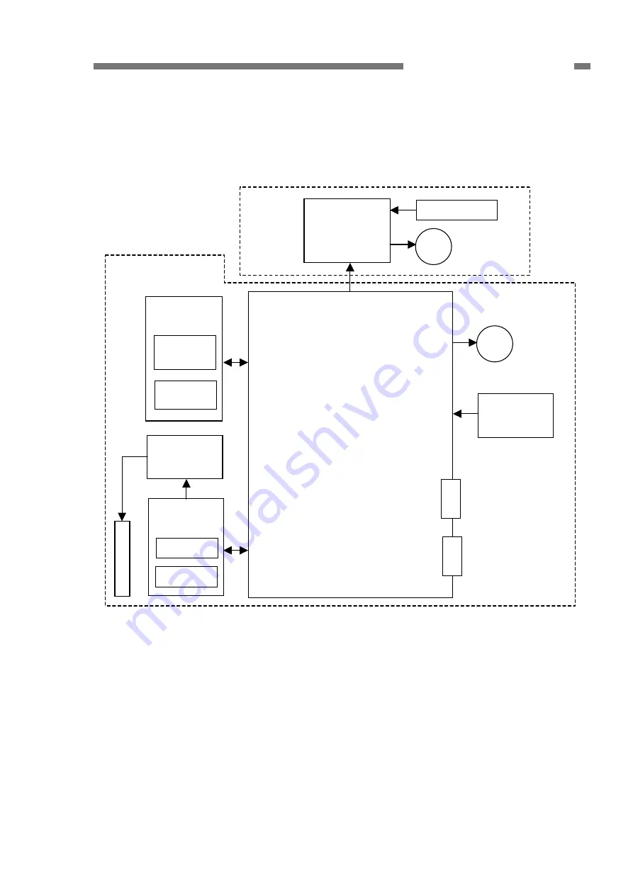
The figure below shows the outlines of
the block diagram.
Figure 2-103
The main PCB is built in the flatbed
assembly. This PCB has the IC to control
the scanner, which controls this machine but
has no firmware. The low level driver (LLD)
installed in the computer has the functions
as a firmware.
The CCD PCB, the inverter PCB and the
fluorescent lamp (CCFL) are built in the
reading unit, which is connected to the main
PCB via the CCD PCB.
The electric circuit of the feeder is
connected to the main PCB via the ADF
PCB.
In addition, the machine is equipped
with motors to feed documents and move
the reading unit.
ADF
PCB
C
C
F
L
Sensor
Inverter
PCB
CCD
PCB
Operation
PCB
Switches
(x12)
LCM
Sensors (x2)
M Feed motor
Feeder
USB connector
Main PCB
Power switch
PCB
M
Scanner
motor
Power connector
Flatbed assembly
CCD


