background image

6-5 Assembly/Disassembly of Chassis Unit and Presser 
Holder 

6-5-1 Disassembly of Chassis Unit and Presser Holder 

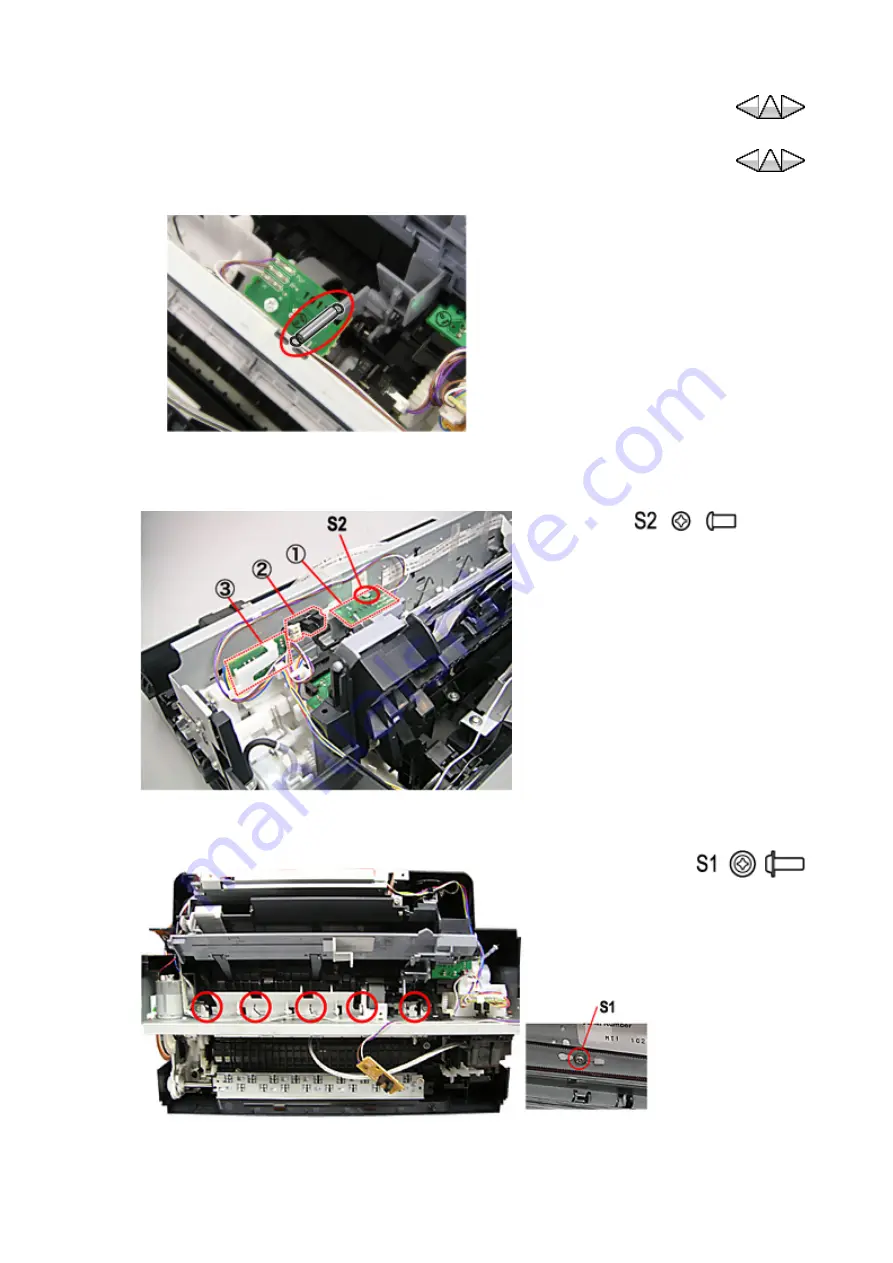
1. Remove the DS spring. 


2. Remove the PE sensor board ass'y (1) fixed by S2 screws. Remove the DS Sensor(2) and 

the PGC Sensor Board ass'y (3). Unplug the PGC sensor board ass'y connector cable. 


3. Remove five pressure holder springs. Remove the pickup roller bushing S1 screw. Remove 

the pickup roller bushing. 


Fig.Part 1-46 Disassembly of the DS spring.


(Binding Head M3 

×

 6) 

×

 1 

Fig.Part 1-47 Disassembly of Sensor Board

(TP M3 

×

 8) 

×

 1 

Fig.Part 1-48 Disassembly of Pickup Roller Bushing

Part 1 -  92

Содержание FAX-JX500

Страница 1: ...AX JX500 CN 1733B014AA FAX JX300 CA 1734B003AA FAX JX300 LAM 1734B004AA FAX JX300 EUM 1734B006AA FAX JX300 ASA 1734B012AA FAX JX300 CN 1734B014AA FAX JX300 KR 1734B016AA FAX JX200 US 1735B002AA FAX JX200 LAM 1735B004AA FAX JX200 EUM 1735B006AA FAX JX200 EMB 1735B007AA FAX JX200 GB 1735B008AA FAX JX200 AU 1735B011AA FAX JX200 CN 1735B014AA FAX JX200 KR 1735B016AA FAX JX201 ASA 1898B012AA FAX JX201 ...

Страница 2: ...on will release technical information when necessary When substantial changes are made to the contents of the manual Canon will issue a revised edition The following do not apply if they do not conform to the laws and regulations of the region where the manual or product is used Trademarks Product and brand names appearing in this manual are registered trademarks or trademarks of the respective ho...

Страница 3: ...the product Part 2 Technical Reference New technology and technical information of the product Part 3 Appendix Schematic and Specifications REFERENCE This manual does not provide sufficient information of disassembly and reassembly procedures Refer to the graphics in the separate Parts Catalog FAX JX500 JX300 JX200 JX201 Service Manual I MANUAL OUTLINE I Manual Outline ...

Страница 4: ...Blank Page FAX JX500 JX300 JX200 JX201 Service Manual ...

Страница 5: ...cautions for Hard Power ON OFF Mode 3 5 Precautions for Soft Power ON OFF Mode 3 6 Precautions for Power Save Mode 3 7 FINE Cartridge Handling 3 8 Contact Sensor Handling 3 9 Warning for Lithium Battery Replacement and Disposal For Germany 3 10 Special Notes on Servicing For California U S A 4 Repair 4 1 Action in the Event of Abnormality All Clear 4 2 Precautions for Main Board ass y Replacement ...

Страница 6: ...rvice Mode 5 12 1 1 Bit Switch 5 12 2 2 Numeric Parameter 5 12 3 3 FAX TYPE 5 12 4 4 NCU 5 12 5 5 TAM 5 12 6 Clear 5 12 7 ROM Version 5 12 8 Report 5 13 Localization Setting 5 14 Selective Function in Localization Setting 5 15 Localization Setting Function 6 Assembly and Disassembly 6 1 Precautions for Assembly and Disassembly 6 2 Assembly Disassembly of Outside Appearance 6 3 Assembly Disassembly...

Страница 7: ...Separation 1 2 New Position of Contact Sensor ass y 1 3 ROM Version up with USB connection 1 4 Ink Level Detection Function 1 5 FINE Cartridge Position Adjustment Function 1 6 Cleaning Mode and Suction Part 3 Appendix 1 Block Diagram 2 Position of Connector 3 Specifications II Table of Contents ...

Страница 8: ...Blank Page FAX JX500 JX300 JX200 JX201 Service Manual ...

Страница 9: ...Part 1 Maintenance R2 Confidential Part 1 1 ...

Страница 10: ...Blank Page FAX JX500 JX300 JX200 JX201 Maintenance Part 1 2 ...

Страница 11: ... To set the language to be displayed on the LCD None Perform in the service mode 1 min Waste ink counter resetting EEPROM settings At waste ink absorber replacement To reset the waste ink counter None 1 min Waste ink amount setting EEPROM settings At Main Board ass y replacement To set the waste ink amount to the waste ink counter None 2 min Print head alignment At FINE Cartridge replacement At Ma...

Страница 12: ...lity is not satisfying and not improved by print head cleaning To improve nozzle conditions Machine buttons 3 min FINE Cartridge replacement When an FINE Cartridge becomes empty To replace the empty FINE Cartridge None 2 min Paper feed roller cleaning When paper does not feed properly To clean the paper feed rollers Machine buttons 2 min Bottom plate cleaning When the back side of the paper is sme...

Страница 13: ... 641 QY9 0035 000 To protect the machine s sliding portions Grease MOLYKOTE EM D110 HY9 0023 000 To move the timer gear smoothly apply the grease on timer gear inside diameter To move the double gear smoothly apply the grease on the double gear inside diameter Z21 Timer Gear Z22Z40 Double Gear Grease FLOIL KG 107A QY9 0057 000 To move the carriage smoothly apply the grease the CHASSIS UNIT guide r...

Страница 14: ...Blank Page FAX JX500 JX300 JX200 JX201 Maintenance Part 1 6 ...

Страница 15: ...our sorts of cyclical blinkings occur in maximum e g FAX JX500 JX300 JX200 JX201 Maintenance 2 TROUBLESHOOTING MAIN DISPLAY 2sec cyclical blinking ERROR DISPLAY 1 10 10 FaxTel Standby 2sec cyclical blinking 2 LOAD PAPER Printer error 2sec cyclical blinking 3 10 10 FaxTel Standby 2sec cyclical blinking 4 REC D IN MEMORY Memory RX 2sec cyclical blinking 5 10 10 FaxTel Standby 2sec cyclical blinking ...

Страница 16: ...s not exist The FAX transaction exceeds the specifications The TAM tarnsaction exceeds the specifications Erase the memory Not played IMC existed NEW MESSAGE Not played IMC exists in the TAM mode OFF condition Play the not played IMC Low ink level RECOMEND NEW CRT The ink level is low Ink LED indication pattern ON Ink low1 Blinking Ink low2 No ink Ink volume unknown Replace the FINE cartridge with...

Страница 17: ...N regardless of resolving this error FINE cartridge not installed PUT IN CARTRIDGE Any FINE cartridge is not recognized when starting printout or suction Install a FINE cartridge Waste ink soon runout INK ABS NEAL FUL The waste ink level exceeds the specified 95 when starting the soft ON OFF or suction Press Stop key Cartridge error CHECK INK The FINE cartridge is not supported Install a CANON rec...

Страница 18: ...rror CHECK 6000 An error occurs to the paper feed encoder signal Timing sensor unit Timing slit disk film Feed roller Reader Unit Main Board ass y Paper feed motor 6 times Internal temperature error CHECK 5400 The internal temperature is not proper Main Board ass y Carriage unit 7 times Waste ink absorber full CHECK 5B00 The waste ink absorber is full Ink absorber kit 8 times Print head temperatur...

Страница 19: ...ot set The printout is not executed while receiving the FAX simultaneously No telephone number NO TEL The one touch speed dialing button or coded speed dialing code you entered has not been registered Register the one touch speed dialing button or coded speed dialing code Memory full MEMORY FULL The fax s memory is full because it has received too many documents or a very long or detailed document...

Страница 20: ...rd ass y The LCD is not displayed partially Perform the button and LCD test in the service mode Check if the LCD is displayed without missing segments Check the connection between the operation panel the reader unit and the Main Board ass y Flat cable PANEL MAIN Operation panel unit Main Board ass y Paper feed defect Multi feeding skewed feeding no feeding Check the inside of the main unit Check i...

Страница 21: ... Board ass y 2 Paper gets smeared Feed several papers Perform the bottom plate cleaning Clean the paper path with a cotton swab or a cloth Clean the drive unit sub rollers A part of a line is missing on the printed paper Clean the FINE Cartridge 5 times FINE cartridge Printing quality is poor Main Board ass y 2 Black ink is not ejected Remove and re install the FINE Cartridge Remove foreign materi...

Страница 22: ...tion between the reader unit and the Main Board ass y Reader Unit Main Board ass y 1 Streaks or smears on the scanned image Clean the contact sensor ass y and the drive unit Check the connection between the reader unit and the Main Board ass y Reader Unit Main Board ass y 1 Document slipping over the roller copied image enlarged or document not separated Clean the friction tab the document feed ro...

Страница 23: ...he power cord is bundled or knotted If you detect smoke unusual smells or strange noises around the machine immediately unplug the machine at the power supply and call for service Periodically unplug the machine and use a dry cloth to wipe off any dust or dirt collected on the plug and the power outlet If the machine is placed at a location exposed to a lot of dust smoke or high humidity the dust ...

Страница 24: ...e on a thick rug or carpet Do not place the machine with its back attached to the wall Power supply Ensure that the area around the power outlet is kept clear at all times so you can easily unplug the power cord if necessary Never remove the plug by pulling on the cord Do not use an extension lead cord Working around the machine Never put your hands or fingers in the machine while it is printing D...

Страница 25: ... on driver ICs etc on PCBs in particular ICs with heatsinks z FINE Cartridge aluminum plate 3 2 3 Fire It is dangerous to throw lithium batteries and parts and components containing flammable substances such as cartridges etc into fire Such parts and components must be disposed of in accordance with local laws and regulations 3 2 4 Ignition When using solvents such as alcohol etc while conducting ...

Страница 26: ...nstead cotton clothes and rubber soled shoes z Avoid working in a carpeted area z Before work touch the grounded earth terminals of the main unit in order to discharge any static electricity z Use a wrist strap and earth the metal parts of the main unit Use 1MΩ resistance integrated current control type z PCBs and electrical elements must be lifted by holding the edges and avoid direct contact wit...

Страница 27: ...n the electrical circuits the circuitry may short out and be damaged If ink is leaking the power must be switched off 3 3 Product Transportation Please follow procedures below when to transport repaired products 1 Start the MFP service mode Refer to Part1 5 6 Selective Function in MFP Service Mode 2 Open the operation panel Remove the FINE Cartridge 3 Set to the soft power ON 3 4 Precautions for H...

Страница 28: ...The control memory saved data is saved as the backup in the EEPROM and the flash memory if electric service interrupts or if the Power Code is unplugged z User registration data basic setting transmission setting etc z TEL No data One touch speed dialing coded speed dialing and group dialing z Activity report data z SSSW z RTC data z Received image z TAM massage z Condition before the hardware pow...

Страница 29: ...y while all conditions below do not satisfy z In the service call error Pressing and holding ON OFF is operative in some service call errors z During FAX communication z During Fax Tel switching During TEL ringing z During the automatic redial standby z During the received image printout z During ADF operation 3 5 3 FAX Operation during Soft Power OFF Mode The operations below are available during...

Страница 30: ...defect is detected during the soft power ON FAX JX500 FAX JX300 only DATA TROUBLESHOOTING User registration data Inform the operator of the error Press Stop Return the user registration data to the preset value TEL No data Inform the operator of the error Press Stop Delete the TEL No data Activity report data Delete the data SSSW Return to the preset value Received image Delete the data TAM messag...

Страница 31: ...The following is the flowchart from the flash ROM Fig Part 1 1 Recovery during Soft Power ON Download PDF ...

Страница 32: ...it z DTMF detection 3 7 FINE Cartridge Handling 3 7 1 Opening FINE Cartridge Package Never open the FINE cartridge package until you start using the cartridge Remove the protective seal on the nozzle carefully when installing the FINE cartridge to the printer 3 7 2 Nozzle Protection Never touch or wipe the FINE cartridge nozzle with a tissue paper etc It prevents from fixing the ink at the nozzle ...

Страница 33: ...isposal For Germany 3 9 1 Replacement English Risk of explosion if battery is replaced by an incorrect type German Explosionsrisiko falls Batterie nicht mit vorgeschriebenem Baterrietypus ersetzt wird 3 9 2 Disposal English Dispose of used batteries according to the local regulations German Batterienentsorgung gemaess lokalen Vorschriften 3 10 Special Notes on Servicing For California U S A Includ...

Страница 34: ...Blank Page FAX JX500 JX300 JX200 JX201 Maintenance Part 1 26 ...

Страница 35: ...ress and hold Stop key 3 Press and hold ON OFF key 4 ON OFF LED turns ON Beep sounds 5 Release Stop key 6 Press Stop key twice Releasing Stop key 7 Release ON OFF key Execute all clear in the MFP service mode in the following procedure 8 Press ON OFF key Turn the power supply OFF 9 Press and hold Stop key 10 Press and hold ON OFF key 11 ON OFF LED turns ON Beep sounds 12 Release Stop key 13 Releas...

Страница 36: ...15 Start the localization setting 1 Press key and Select 3 FaxType Set Press Start key 2 Select proper FAX type by pressing Press Start key Part 1 28 ...

Страница 37: ... Confirm the connection between cables and connecters Never drop the ferrite core Never damage electronic devices by electricity Wait approximately 1 minute after unplugging the AC adapter and then disassemble Main Board ass y This prevents from damaging Main Board ass y by discharging storage electricity in the condenser Never touch the Timing Slit Strip Film and the Timing Slit Disk Film Never c...

Страница 38: ...value as 10 is the maximum limit Part1 5 8 9 13 Waste Ink Counter Level Registration Input 0 90 according to the number of printout copies 14 000 copies 100 if the waste ink counter value is not succeeded 4 2 3 Button Type Lithium Battery Installation Button type lithium battery is not installed to Main Board ass y Purchase and install new battery The model number is as follows z Number CR2032 4 3...

Страница 39: ...eplaced 1 When removing the screws mark the red screw holes Fig Part 1 2 Mark the screw holes 2 When installing the motor position each screw to the mark and fasten them 3 After replacement be sure to perform the service test print and confirm that no strange noise or faulty print operation due to dislocation of the belt or gear or out of phase motor etc occurs The red screws securing the paper fe...

Страница 40: ...hing the carriage rail make sure that the boss fits into the hole and to the mark made in step 1 then fasten the screws 3 Be sure to perform the confirmation test detailed below confirm that the print quality is proper and the FINE Cartridges are not contacting the paper Main chassis adjustment After installing the main chassis be sure to perform the confirmation test detailed below confirm that t...

Страница 41: ...he head to paper distance in the following procedures Procedures for adjusting the head to paper distance 1 At the bottom edge of the boss beside the red screw on each side of the chassis put a mark to indicate the current position See the step 1 of the carriage rail adjustment above 2 Loosen the red screws and adjust the head to paper distance To prevent the ink cartridges from contacting the pap...

Страница 42: ...4 6 Grease Application 1 Apply grease on the upper surface much more than the reverse side of the front surface Fig Part 1 4 Grease application 1 3 Part 1 34 ...

Страница 43: ...y grease from the axis inserted side for both gears For applying grease on the gear inside diameter evenly when inserting the CS gear frame 3 Never run over grease Fig Part 1 4 Grease application 2 3 Part 1 35 ...

Страница 44: ... PART SHALL BE FREE FROM ANY GREASE Reuse by wiping off is not allowed Fig Part 1 4 Grease application 3 3 Part 1 36 ...

Страница 45: ...p 4 locations 9 Slider shaft sliding portion bottom case top MOLYKOTE PG 641 Quarter drop 2 locations 10 Swing Arm Release Cam Carriage sliding portion MOLYKOTE PG 641 1 drop 2 locations 11 Eject roller sliding portion MOLYKOTE PG 641 Quarter drop 12 Trigger arm carriage sliding portion FLOIL KG107A Half drop Platen Lower Eject Roller 13 Eject roller sliding portion FLOIL KG107A Half drop 2 locati...

Страница 46: ...e free from any grease Reuse by wiping off is not allowed 24 Carriage Part shall be free from any grease Reuse by wiping off is not allowed Head Guide 25 Head Guide Head Insert Area Part shall be free from any grease Reuse by wiping off is not allowed Part 1 4 Repair Part 1 38 ...

Страница 47: ... to reads bit switch tables FAX JX500 JX300 JX200 JX201 Maintenance 5 SERVICE SWITCHES Fig Part 1 5 Bit Switch Display The setting is 1 The setting is 0 BIT FUNCTION 1 0 0 Service error code Output Not Output 1 Error dump list Output Not Output 2 Not used 3 Not used 4 Not used 5 Not used 6 Not used 7 Receive image transfer Yes No Boldfaced figures are the default setting Fig Part 1 6 How to Read B...

Страница 48: ...ion Part 1 5 11 FAX Service Mode Function for the details of the SSSW Service Software Switch parameter default Indicates a setting range of 1 to 99 NO FUNCTION SELECTION RANGE DEFAULT SETTING 02 RTN signal transmission condition 1 to 99 10 10 23 FAX TEL switching function signal detection level 0 to 7 4 43 dbm Indicates that the default 4 corresponds to a value of 43 dbm For details on the relati...

Страница 49: ...ode 1 2 Press keys to select a function 3 Press Start key to execute the function 4 Press Numeric keys at each setting mode to change the value 5 Press Start key to valid the changed setting z Press Menu key when returning to the user maintenance mode z Press Stop key when returning to standby 10 10 Tel Fax Standby CS CLEANING User maintenance mode 10 10 Tel Fax User maintenance mode Part 1 41 ...

Страница 50: ...anual ALIGN PRINT HEAD Enter in the user maintenance mode Select the item The pattern is printed out A proper FINE cartridge position is set from the pattern FINE cartridge position adjustment value printout HEAD ALIGN VALUE Enter in the user maintenance mode Select the item The current FINE cartridge position adjustment value and pattern are printed out Roller cleaning ROLLER CLEANING Enter in th...

Страница 51: ...top key is released 7 Release ON OFF key z Set to soft power off temporarily and then execute Step 2 7 above when returning to the service mode z The user mode starts when releasing ON OFF key before Step 6 is completed z The user mode starts when pressing ON OFF key during Step 7 is standby CANON Entering in the service mode ON OFF LED blinks Idle Standby ON OFF LED turns ON Part 1 43 ...

Страница 52: ...function selection Indication does not change 3 Press ON OFF key to execute the selective function z Return to standby if you press ON OFF key after pressing Stop key more than the number of selective functions z ON OFF LED blinks while performing the pre execution initialization or executing each function z The setting paper delivers The carriage moves to the FINE cartridge replacement position w...

Страница 53: ... 3 USA CND 4 EUR 5 AUS 6 ASIA 7 CHN 8 TWN 9 LTN 10 Return to the region setting 6 FINE cartridge refreshing 7 Return to the function selection menu 8 Return to the function selection menu 9 Return to the function selection menu 10 Return to the function selection menu 11 Return to the function selection menu 12 Operation panel check 13 Waste ink counter level registration 14 Return to the function...

Страница 54: ...le of Service Pattern Printout Service pattern output item 1 Model name 2 EEPROM version 3 Waste ink counter level 4 Information for factory 5 Information for factory 6 Vertical check pattern No ejection of ink 7 Region 8 Carriage uneven pattern Uneven pattern should not be obvious 9 Ruled line misalignment pattern Ruled line misalignment should not be obvious 10 Information for factory Fig Part 1...

Страница 55: ...5 8 3 2 EEPROM Information Printout Print out EEPROM information Sample of EEPROM information printout Fig Part 1 10 EEPROM information output Part 1 47 ...

Страница 56: ...REG Automatic user range M_REG Manual user range z 11th line PAGE Pieces of ASF printout 5 5 All total PP plain paper HR MP High grade Paper Matte Photo PR SP SG Photo Paper Pro Photo Paper Plus Glossy Semi Glossy Paper GP Glossy Paper PC Postcard EV Envelop z 12th line Scanner z 13th line SC Number of total scanning SCAN_ER Scanner error status history 6 6 ER0 The latest record ER1 Next to the la...

Страница 57: ...ress Stop key 4 times Select the waste ink counter clear item Press ON OFF key Refer to Part1 5 5 How to Enter in MFP Service Mode Part1 5 6 Selective Function in MFP Service Mode 3 Select the counter clear item according to the number of pressing Stop key NUMBER OF PRESSING STOP KEY COUNTER CLEAR ITEM ON OFF LED STATUS 0 Set the main waste ink counter to 0 ON 1 Set the platen waste ink counter to...

Страница 58: ...ct the region setting item Press ON OFF key Refer to Part1 5 5 How to Enter in MFP Service Mode Part1 5 6 Selective Function in MFP Service Mode 3 Press Stop key to select the counter clear item Press ON OFF key 5 8 7 6 FINE Cartridge Refreshing Follow the same procedure as the driver batch refreshing NUMBER OF PRESSING STOP KEY REGION VALUE ON OFF LED STATUS 0 No change ON 1 JPN OFF 2 KOR ON 3 US...

Страница 59: ...art key 4 Press Start key 5 Press Start key 6 Press TAM 1 Delete 1 Play 1 0 9 1 FAX JX500 FAX JX300 only 7 Press On Off Receive Mode Resolution Menu 01 09 keys 8 Press Hook Start Stop keys 9 Press Stop key 10 Press Stop key 11 All LCD segments indicate All LCD segments does not indicate LED TEST All LED s turn ON On Off TDP123456789 0 Indication disappears when pressing any applicable key 1 ABCDEF...

Страница 60: ...B key C Receive Mode Resolution key D Menu key E One touch speed dialing 01 key F One touch speed dialing 02 key G One touch speed dialing 03 key H One touch speed dialing 04 key I One touch speed dialing 05 key J One touch speed dialing 06 key K One touch speed dialing 07 key L One touch speed dialing 08 key M One touch speed dialing 09 key 3 Applicable key LCD APPLICABLE KEY A key B key C key D ...

Страница 61: ...he waste ink counter amount register item according to the number of pressing Stop key Press ON OFF key 4 Select the value according to the number of pressing Stop key 10 each Input 0 90 according to the number of printout pages in past criteria 14 000 100 if the waste ink level is not succeeded to the waste ink counter NUMBER OF PRESSING STOP KEY WASTE INK COUNTER LEVEL REGISTRATION ITEM ON OFF L...

Страница 62: ...e 1 2 Press keys to select a function 3 Press Start key to execute the function 4 Press numeric keys at each setting mode to change the value 5 Press Start key to valid the setting z Pressing Menu key returns to 1 FAX service mode z Pressing Stop key returns to the standby 10 10 Tel Fax Standby MEMORY REFERENCE User mode 1 BIT SWITCH Standby 1 BIT SWITCH Standby Part 1 54 ...

Страница 63: ...X Service Mode Function FAX SERVICE MODE a 1 BIT SWITCH BIT Valid SW 7 6 5 4 3 2 1 0 Invalid SW01 SW02 SW03 SW04 SW05 SW06 SW07 SW08 SW09 SW10 SW11 SW12 SW13 SW14 a Fig Part 1 11 FAX Service Mode 1 5 Part 1 55 ...

Страница 64: ... switching 24 0 15 Simulated RBT transmission level during FAX TEL switching 25 15 300 Line acquisition time during FAX TEL switching 26 10 120 CNG monitoring time during TAM 27 0 45 CNG detection level during TAM 28 0 9 CED detection level 29 1 60 Number of TSI comparative digit during TEL number verification 30 0 5 V 34 primal channel symbol minimum speed 31 0 13 V 34 primal channel symbol maxim...

Страница 65: ...ilable 16 IRELAND Available 17 ITALY Available 18 N L Available 19 NORWAY Available 20 POLAND Available 21 PORTUGAL Available 22 RUSSIA Available 23 SLOVENIA Available 24 SPAIN Available 25 SWEDEN Available 26 SWISS Available 27 U K Available 28 SAF Available 29 Australia Not available 30 N Z Not available 31 ASIA Not available 32 HONG KONG Not available 33 MALAYSIA Not available 34 SINGAPORE Not ...

Страница 66: ... c 4 NCU 1 TONE PLUSE 2 DIAL TONE 1 3 DIAL TONE 2 4 BUSY TONE 5 REORDER TONE 6 AUTO RX 7 CNG DETECT d Fig Part 1 11 FAX Service Mode 4 5 Part 1 58 ...

Страница 67: ...oll saver response with ICM 08 0 9999 Number of toll saver response without ICM 09 0 9999 DT number of detection K1 H0252 during TAM 10 0 9999 Waiting time until starting ICM recording 11 0 9999 Missing number 12 0 9999 T1 timer 13 0 9999 T2 timer 14 0 9999 T3 timer 15 0 9999 T4 timer 16 0 9999 Signal detection table 17 0 9999 Signal detection level 18 0 9999 Number of signal frequency 19 20 CLEAR...

Страница 68: ...e 7 V 34 activity report output Available Not available BIT FUNCTION 1 0 0 NL equalizer selection Available Not available 1 Echo protection tone to V 29 Available Not available 2 Reception sensibility setting during TCF reception at V 17 Not available Available 3 DIS bit33 or more transmission Not available Available 4 DIS twice hearing Available Not available 5 1st DIS inobservance Available Not ...

Страница 69: ...Not used 4 MR MMR mode prohibition Not available Available 5 MMR mode prohibition Not available Available 6 Not used 7 Not used BIT FUNCTION 1 0 0 1 page timeout transmission 0 0 1 8 min 0 1 1 16 min 1 0 1 32 min 1 1 1 64 min 1 Bit 1 Bit 0 1 2 1 page timeout HT transmission 0 0 2 8 min 0 1 2 16 min 1 0 2 32 min 1 1 2 64 min 2 Bit 3 Bit 2 3 4 1 page timeout reception 0 0 3 8 min 0 1 3 16 min 1 0 3 ...

Страница 70: ... Not available BIT FUNCTION 1 0 0 Not used 1 TCF check 1 during the V 17 mode reception Available Not available 2 Tone signal 1 400 Hz transmission during the FAX TEL switching Not available Available 3 Not used 4 DCN transmission during the T1 timeout Available Not available 5 Not used 6 Not used 7 Not used BIT FUNCTION 1 0 0 Not used 1 Not used 2 Paper cutting setting when transmitting a long do...

Страница 71: ...lable 6 Tone Pulse user setting prohibition Not available Available 7 Not used BIT FUNCTION 1 0 0 HOME FAX function 000 countries other than applicable destination 001 Australia 010 New Zealand 011 Denmark 100 Finland Others Reserve 1 2 3 Hong Kong CI Available Not available 4 Reception mode DRPD addition setting Available Not available 5 Not used 6 Not used 7 Manual transmission function prohibit...

Страница 72: ...to 500 19 Simulated ring back tone cadence ON time 10 to 500 20 Simulated ring back tone cadence OFF time short 0 to 300 21 Simulated ring back tone cadence OFF time long 10 to 500 22 Not used 0 to 10 23 CNG detection level during FAX TEL switching 0 to 45 24 Simulated RBT transmission level during FAX TEL switching 0 to 15 25 Line acquisition time during FAX TEL switching 15 to 300 26 CNG monitor...

Страница 73: ...ringing time during manual automatic switching 1 to 60 40 Maximum number of ring counting during the automatic ringing 1 to 99 41 Not used 10 to 1000 42 Pre posing during DT not detected 100 to 500 43 Pulse dial setup time pulse dialing 0 to 9999 44 Pulse dial clear time pulse dialing 0 to 9999 45 Not used 0 to 4 46 Not used 1 to 2400 47 Not used 0 to 10 48 Not used 0 to 10 49 TEL DTMF transmissio...

Страница 74: ...and the numeric parameter 1 Bit SW z SW01 Bit 0 to Bit2 and Bit 6 Do not use the bits z SW02 Bit 0 Bit 1 Bit 3 and Bit 5 Do not use the bits BIT FUNCTION 1 0 0 Not used 1 Not used 2 Not used 3 DT Detection during TAM Available Not available 4 ROT detection while playing ICM Available Not available 5 No sound detection Available Not available 6 Not used 7 No sound time recording Available Not avail...

Страница 75: ...ting the OGM play 0 to 9999 200 04 Number of times TAM response when TAM set is not carried out 0 to 9999 15 05 Modem output level ROM message 0 to 9999 14 06 Modem output level RAM message 0 to 9999 2 07 Number of toll saver response with ICM 0 to 9999 2 08 Number of toll saver response without ICM 0 to 9999 5 09 Number of DT detection during TAM 0 to 9999 5 10 Waiting time until starting the ICN...

Страница 76: ...hers 63 z No 16 Signal detection table Poland UK 0 AUS SAF 1 China China2 French Portugal 3 Sweden 6 Belgium 8 Finland Holland Spain 10 Austria Denmark Germany Italy Swiss 11 USA 12 Russia 13 HK 14 Korea 15 Others 5 z No 17 Signal detection level Canada USA 3 Korea Taiwan 5 Others 6 z No 18 Number of signal frequency CHN 3 USA CAN LAM BRA MEX 2 Others 4 Part 1 68 ...

Страница 77: ...ure below 1 Start the FAX service mode 2 Press key Select CLEAR 3 Press Start key 4 Press keys to select an item 5 Press Start key Execute the clear 1 BIT SWITCH Standby CLEAR TEL TEL Clears the TEL number data USER SW Clears the user registration data ALL Clears all data Perform the TYPE setting after the all clear Part 1 69 ...

Страница 78: ...t ROM VERSION 3 Press Start key 4 The indication switches when pressing Start key 1 BIT SWITHC Standby ROM VERSION ROM Ver 0 26 1 ROM Ver 0 26 Pressing Start key 2 2006 08 29 Pressing Start key 3 EUR Destination is indicated Pressing Start key 4 MODEM Ver 8 63 Modem version is indicated Pressing Start key Return to 1 Part 1 70 ...

Страница 79: ...ne Follow the procedure below 1 Start the FAX service mode 2 Press key to select REPORT 3 Press Start key 4 Press Start key again to print out the system data list 1 BIT SWITHC Standby REPORT SYSTEM DATA LIST Fig Part 1 12 Sample of System Data List Part 1 71 ...

Страница 80: ...alization Setting 1 2 Press key to select a function z Pressing Stop key returns to Soft Power Off localize Localization setting top menu 1 ROM Version Press Start key to indicate the ROM version Press Stop key to return the mode 2 FaxType Disp Press Start key to indicate the current FAX type Press Stop key to return the mode 3 FaxType Set Press Start key to enter in Fax Type setting Press keys to...

Страница 81: ...AX TYPE EUROPE1 EUROPE2 AUSTRIA BELGIUM CZECH DENMARK FINLAND FRANCE GERMANY HUNGARY IRELAND ITALY N L NORWAY POLAND POLTUGAL RUSSIA SLOVENIA SPAIN SWEDEN SWISS U K SAF LUXEMBOURG GREECE Return to EUROPE1 Fig Part 1 13 Localization Setting Function List Part 1 5 Service Switches Part 1 73 ...

Страница 82: ...Blank Page FAX JX500 JX300 JX200 JX201 Maintenance Part 1 74 ...

Страница 83: ...ch the main frame CAUTIONS for the red screw z Remove the paper feed motor installation red screw only when replacing the Paper Feed Motor Unit Never loosen the red screw for other cases Refer to Part 1 4 5 1 Paper feed motor adjustment z Never loosen the carriage rail red screw other than for replacing the carriage Check if the FINE Cartridge is not in friction with a board as the paper gap carri...

Страница 84: ...or the details Never leave the timing slit disk film anywhere it deforms when removing the paper feed roller ass y Never touch the slit pattern of the timing slit disk film Never adhere grease to the timing slit disk film Never reuse the grease removed part Replace the timing slit disk film with new one if grease is adhered to the timing slit disk film Remove the DS sensor 2 before removing the B ...

Страница 85: ...der unit cable with the CS drive gear ass y and the Main Unit 6 1 5 Precautions for Reader Unit Slide the CS support stop rightward when laying down the reader unit Fig Part 1 14 Precautions for Reader Unit Cable Wiring Fig Part 1 15 Precautions for Reader Unit Part 1 77 ...

Страница 86: ...Remove the rear cover 2 Pull up the pawl on the center of the cover arm stopper 1 Slide the cover arm stopper 2 downward Remove six main case unit screws Remove the head guide TP BH M3 8 2 Fig Part 1 16 Disassembly of the Rear Cover TP BH M3 8 4 BINDING HEAD M3 6 2 Fig Part 1 17 Disassembly of Main Case Unit Part 1 78 ...

Страница 87: ...ble 1 between the Main Board ass y and the Operation Panel Unit the Main Case Unit Pull up two pawls on the reverse side 2 Pull two pawls on the front side 3 Remove the main case unit by lifting it up Fig Part 1 18 Assembly of Side Cover Fig Part 1 19 Location of Main Case Unit Pawl Part 1 79 ...

Страница 88: ...d ass y cables 1 The PGC Sensor Board ass y cables 2 The Speaker ass y cables 3 Lead cables to the metal groove If the main case unit is not installed due to the tilt of the pressing plate unit rotate the paper feed motor to any direction Tip up pressing plate unit Install the main case unit Never touch the timing slit disk film Fig Part 1 20 Outside Appearance Cable Wiring Fig Part 1 21 Outside A...

Страница 89: ...chment position of The Reader Unit cables 1 The Carriage Unit cable 2 The Reader Unit GND cable 3 The Carriage Motor cables 4 The Reader Unit cables 5 The Paper Feed Sensor Board ass y cables 6 Ferrite core of the Handset Modular Board ass y Fig Part 1 22 Outside Appearance Cable Wiring Fig Part 1 23 Outside Appearance Cable Wiring Fig Part 1 24 Outside Appearance Cable Wiring Part 1 81 ...

Страница 90: ...y cables 5 Tape attachment position of the PE Sensor Board ass y cables 1 The Ferrite core of the Panel Main Flat Cable Lead the upper cable only to the ferrite core 2 Tape attachment position of the Panel Main Flat Cable Fig Part 1 25 Outside Appearance Cable Wiring Fig Part 1 26 Outside Appearance Cable Wiring Part 1 82 ...

Страница 91: ... PS MAIN cable 2 Remove the sub bottom cover screw S1 Remove the sub bottom cover 1 and the PS MAIN cable 2 3 Unplug all cables connected to the Main Board ass y Remove three Main Board ass y screws Remove the Main Board ass y Fig Part 1 27 Disassembly of Power Supply TP M3 8 1 Fig Part 1 28 Disassembly of Sub Bottom Cover Binding Head M3 6 3 Fig Part 1 29 Disassembly of Main Board ass y Part 1 83...

Страница 92: ...pply and Main Board ass y Assemble in the reverse order of disassembly 1 Install the main board Ass y between pawls on the downward left of the main board plate Improper assembly may cause the circuit short TP M3 8 2 Fig Part 1 30 Disassembly of Modular Board ass y and Handset Modular Board ass y Fig Part 1 31 Precaution for Main Board ass y Part 1 84 ...

Страница 93: ... REMARK 1 PGC Sensor Board ass y 2 Speaker ass y 3 Handset Modular Board ass y 4 Carriage Unit 5 Reader Unit Plug to the contact sensor ass y 6 Modular Board ass y 7 Operation Panel Unit Use the PANEL MAIN flat cable 8 Paper Feed Sensor Board ass y 9 ROM Ver Up Board With Cable Use for ROM update only 10 Carriage Motor 11 Paper Feed Motor 12 Power Supply Unit Use the PS MAIN cable Part 1 85 ...

Страница 94: ...ndset 3 The Paper Feed Motor cables 4 Tape attachment position of the power supply cables Fig Part 1 33 Modular Board ass y Cable Wiring Fig Part 1 34 Handset Modular Board ass y Cable Wiring Fig Part 1 35 PS MAIN Cable Wiring Part 1 86 ...

Страница 95: ...connection slit on the right side Remove the connection by sliding the access cover unit leftward 2 Remove three access cover unit S1 screws on the reverse side Remove the operation panel unit Pull up the two pawls on the operation panel unit as tracing an arc Unplug three cables connected to the operation panel unit Fig Part 1 36 Disassembly of Access Cover Unit TP M3 8 3 Fig Part 1 37 Disassembl...

Страница 96: ...rse side Remove the hook lever cover Remove the hook cover Remove the cover sensor board Ass y S5 screws The cover sensor board ass y screws are tighten with the ground wire 5 Remove the screws fixing the hook lever cover and the hook sensor board ass y Remove the hook sensor board ass y Fig Part 1 38 Disassembly of Panel Cover TP M3 6 3 Fig Part 1 39 Disassembly of Hook Lever Cover TP M3 6 1 Fig ...

Страница 97: ...sor board ass y with the ground wire Fix the ground terminal at the rotation stopper 1 Clip the cable with the slit 2 Never interfere the cable with the hook lever cover Install the operation panel unit and the access cover unit before installing the panel cover Clip three cables to the operation panel unit connector J1 To Panel Main Flat Cable J3 To Hook Sensor Board ass y J4 To Cover Sensor Boar...

Страница 98: ...ensor Board ass y cables 2 The Panel Main Flat Cable cable 1 Install the cover sensor board ass y with the ground wire Fix the ground terminal at the rotation stopper 2 Clip the cable with the slit 2 Never interfere the cable with the hook lever cover Fig Part 1 42 Panel Mail Flat cable wiring Fig Part 1 43 Hook Lever Cover cable wiring Fig Part 1 44 Covoer Sensor Board Ass y cable wiring Part 1 9...

Страница 99: ...J1 the Panel Main Flat Cable J3 The Hook Sensor Board ass y cables J4 The Cover Sensor Board ass y cables Fig Part 1 45 Operation panel cable wiring Part 1 91 ...

Страница 100: ...Remove the DS Sensor 2 and the PGC Sensor Board ass y 3 Unplug the PGC sensor board ass y connector cable 3 Remove five pressure holder springs Remove the pickup roller bushing S1 screw Remove the pickup roller bushing Fig Part 1 46 Disassembly of the DS spring Binding Head M3 6 1 Fig Part 1 47 Disassembly of Sensor Board TP M3 8 1 Fig Part 1 48 Disassembly of Pickup Roller Bushing Part 1 92 ...

Страница 101: ... holder protrusion and the chassis unit slit Separate the pressure holder and the chassis unit together Rotate the PE sensor lever to near direction Remove the PE sensor lever TP M3 8 6 B Tight M3 44 1 Fig Part 1 49 Disassembly of Chassis Unit Fig Part 1 50 Disassembly of Pressure Holder Part 1 93 ...

Страница 102: ...Carriage Unit cable 2 The Carriage Motor cables Install the PE sensor lever spring to the PE sensor lever Align the PE sensor lever connection slit with the pressure holder protrusion Install the PE sensor and the pressure holder together Rotate the PE sensor lever Install the pressure holder to the chassis unit Fig Part 1 51 Chassis Unit cable wiring Fig Part 1 52 Chassis Unit cable wiring Part 1...

Страница 103: ...cm leftward Position the side guide unit under the document left 2 Rotate the document guide to near direction Separate the document guide and the pressing plate unit 3 Pull the side guide unit from the reverse side surface of the pressing plate unit to near direction Separate the side guide unit and the pressing plate unit Fig Part 1 53 Disassembly of Pressing Plate Unit Fig Part 1 54 Separating ...

Страница 104: ...6 6 2 Assembly of Pressing Plate Unit Assemble in the reverse order of disassembly Check if the spring is installed to the proper position when installing the DS sensor board ass y Part 1 96 ...

Страница 105: ...the connection 1 of the drive unit suction tube and the cap blade unit suction tube Remove four drive unit S1 screws Remove the drive unit Remove the speaker ass y and the waste ink absorber 3 Expand the Pick up gear N as shown in the figure 1 Pull out the pickup roller Ass y Fig Part 1 56 Disassembly of Drive Unit TP M3 8 4 Fig Part 1 57 Disassembly of Drive Unit Fig Part 1 58 Disassembly of Pick...

Страница 106: ...2 Check if the connection of the drive unit return lever cam and the return lever when assembling the drive unit 3 Do not remove the lower gear Install the lower gear facing the protrusion 1 number of teethes are larger to right side if removed Install the center gear facing the protrusion 2 number of teethes are fewer to left side Install the right gear 3 positioning the gear to left side Fig Par...

Страница 107: ...7 3 Drive Unit Line Wiring 1 Install the speaker Ass y and the waste ink absorber before assembling the drive unit Face the speaker ass y terminal on the right side 2 Attach the speaker unit connection of the drive belt Fig Part 1 62 Suction Tube Connection Fig Part 1 63 Assembly of Return Lever Spring Fig Part 1 64 Speaker Unit cable wiring Part 1 99 ...

Страница 108: ...1 Cable of PGC Sensor Board ass y cables 2 Cable of Speaker ass y cables 3 Cable of ASF Sensor Board ass y cables 4 Lead cables to the metal groove Fig Part 1 65 Sensor units cable wiring Part 1 100 ...

Страница 109: ...ve the suction tube securing to the main unit slits 2 Remove the cap slide spring from the cap blade unit bottom surface 1 Move the cap blade unit rightward Pull up two cap blade unit pawls with a driver or an equivalent 2 Pull the cap blade unit upward 3 Fig Part 1 66 Handling Suction Tube Fig Part 1 67 Disassembly of Cap Blade Unit Part 1 101 ...

Страница 110: ...dge to the main unit Secure the suction tube to the main unit with a tape 2 Secure the cap slide spring to the pawls of the cap blade unit and the main unit Install the cap blade unit to the main unit Fig Part 1 68 Assembly of Suction Tube Fig Part 1 69 Assembly of Cap Blade Unit Part 1 102 ...

Страница 111: ...ey rightward once Remove the carriage belt from the idler pulley Remove the idler pulley Never touch the slit pattern of the timing slit film Never adhere grease to the timing slit film Never reuse the grease adhered timing slit film Replace the grease adhered timing slit film with new one Never loosen the carriage unit red screw TP Hexagon Head RED M3 8 except for Part 1 4 5 2 Main chassis and ca...

Страница 112: ...screws S9 Remove the carriage motor 4 Slide the carriage unit rightward Remove the carriage unit Remove the carriage belt from the carriage unit Binding Head M3 6 1 Mach Truss Head M2 6 3 2 Fig Part 1 72 Disassembly of Carriage Motor Fig Part 1 73 Disassembly of Carriage Unit Part 1 104 ...

Страница 113: ...e in the reverse order of removal 6 9 3 Carriage Unit Line Wiring 1 Tape attachment position of Carriage Unit cable Align the convexo concave of the carriage belt 2 and the carriage unit 1 Fig Part 1 74 Carriage unit cable wiring Part 1 105 ...

Страница 114: ...r feed roller Remove the double faced tape attaching the timing slit disk film from the paper feed roller Remove the timing slit disk film Never leave the timing slit disk film anywhere it deforms when removing the paper feed roller ass y Never touch the slit pattern of the timing slit disk film Never adhere grease to the timing slit film Never reuse the grease adhered timing slit film Replace the...

Страница 115: ...om the boss Rotate the eject roller ass y to the indicated position Remove the eject roller ass y 6 10 2 Assembly of Paper Feed Roller ass y Eject Roller ass y Assemble in the reverse order of removal TP M3 8 1 Fig Part 1 77 Disassembly of Spur Base ass y TP M3 8 2 Fig Part 1 78 Disassembly of Eject Roller ass y Slide the bearing to the left Install the eject roller ass y Face the Swing gear side ...

Страница 116: ...Install the timing slit disk to the clearance of the paper feed sensor board ass y Part 1 108 ...

Страница 117: ... S10 when replacing the paper feed sensor board ass y 2 Remove the CS drive gear ass y 1 and the reader unit 2 Never loosen the paper feed motor red screw TP Mach Truss Head RED M2 6 4 other than replacing the paper feed motor Refer to Part 1 4 5 1 Paper feed motor adjustment for the details TP M3 8 3 Binding Head M3 6 1 Binding Head M2 5 2 Fig Part 1 79 Disassembly of Paper Feed Side Plate Fig Pa...

Страница 118: ...motor adjustment for the details 6 11 2 Assembly of CS Drive Gear ass y Reader Unit Assemble in the reverse order of removal Mach Truss Head RED M2 6 4 2 Fig Part 1 81 Disassembly of the Paper Feed Motor Assemble the CS Drive Gear ass y gear Align the convexo concave of the CS drive gear ass y gear and the Reader Unit Part 1 110 ...

Страница 119: ...ecure to the main unit clearance 2 Never pinch the reader unit line with the main unit clearance 1 Tighten the screws in the order of the paper feed side plate the main board plate the contact sensor ass y GND cable Binding Head M3 6 1 Part 1 111 ...

Страница 120: ...le of Reader Unit Never pinch the reader unit line with the main unit clearance 2 Wire the reader unit line as the line clips secure to the main unit clearance 1 The Paper Feed Motor cables Fig Part 1 82 Contact Sensor Ass y cable wiring Fig Part 1 83 Reader Unit cable wiring Fig Part 1 84 Paper Feed Motor cable wiring Part 1 112 ...

Страница 121: ...1 The Reader Unit cables 2 The Paper Feed Sensor Board ass y cables 3 Tepe attachment position of the Reader Unit cables Fig Part 1 85 Part 1 113 ...

Страница 122: ...e outside appearance Refer to Part 1 6 2 1 Disassembly of Outside Appearance 2 Remove two contact sensor ass y screws S11 3 Remove the tape securing the contact sensor ass y cable Unplug the connector Remove the Contact Sensor ass y Fig Part 1 86 The Main Unit TP M2 6 6 2 Fig Part 1 87 Fig Part 1 88 Part 1 114 ...

Страница 123: ...6 12 2 Assembly of Contact Sensor ass y Assemble in the reverse order of removal Part 3 6 Assembly Disassembly Part 1 115 ...

Страница 124: ...Blank Page FAX JX500 JX300 JX200 JX201 Maintenance Part 1 116 ...

Страница 125: ...ss y 2 PES SENSOR ass y 3 DS SENSOR ass y 4 PGC SENSOR ass y 5 ASF SENSOR ass y FAX JX500 JX300 JX200 JX201 Maintenance 7 SENSOR POSITION Fig 1 89 Sensor Position Fig 1 90 Sensor Position Part 3 7 Sensor Position Part 1 117 ...

Страница 126: ...Blank Page FAX JX500 JX300 JX200 JX201 Maintenance Part 1 118 ...

Страница 127: ...Part 2 Technical Reference R2 Confidential Part 2 1 ...

Страница 128: ...Blank Page FAX JX500 JX300 JX200 JX201 Technical Reference Part 2 2 ...

Страница 129: ... Paper 3 Paper guide 1 2 New Position of Contact Sensor ass y FAX JX500 JX300 JX200 JX201 Technical Reference 1 NEW TECHNOLOGY Document set Paper feeding Fig Part 2 1 Document Paper Common Path Separation Printing Document Reading Fig Part 2 2 Contact Sensor ass y Activation ...

Страница 130: ...ble z USB connector z Version up file mot 1 3 2 Preliminary Preparation Copy the necessary software Plug this machine to the computer 1 3 3 Connection with Computer 1 Remove the two screws on the reverse side of the main unit Remove the Rear Cover Attach an insulating tape on the terminal before using ROM Ver Up Board With Cable This prevents from causing short circuit Fig Part 2 3 Disassembly of ...

Страница 131: ...in Board ass y 3 Plug the USB connector to ROM Ver Up Board With Cable Do not plug USB connector to the computer at this time Fig Part 2 4 Cable Connection of Main Board ass y to Ver Up Board Fig Part 2 5 Cable Connection of USB connector ...

Страница 132: ...tor to the computer 7 Cancel the dialog box below asking a driver installation twice if displayed z Print out the user setting data list and the service setting data list The ROM version up deletes the registered data z Never turn this machine OFF until Step 14 is completed after this machine is plugged to the computer at Step 7 This machine may malfunction Execute the all clear after the entire p...

Страница 133: ...devices plug to the computer Fig Part 2 7 Click Get DeviceID on Standard Class if you do not know any appropriate USB Then select the port Fig Part 2 8 9 Click Get DeviceID on Standard Class Check if STA is 80 Fig Part 2 8 Fig Part 2 7 Fig Part 2 8 ...

Страница 134: ...rapidly after the dialog box Fig Part 2 11 disappears 13 Click Get DeviceID on Standard Class again after Power LED turns ON Check the status Check if STA is C0 This status means the writing is completed 14 Unplug the USB connector after the writing is completed Turn the power supply OFF 15 Remove the ROM Ver Up Board With Cable from the machine Fig Part 2 9 Fig Part 2 10 Fig Part 2 11 Fig Part 2 ...

Страница 135: ...16 Start the machine in the normal mode Execute the all clear 17 Check the ROM version in the FAX service mode Check if the version is the latest 18 Turn the power supply OFF Install the machine cover ...

Страница 136: ...en reuse any spent FINE cartridge except for the preceding FINE cartridge e g In a case that you install any spent FINE cartridge Remove the using cartridge Install new FINE cartridge Install the removed FINE cartridge again z The error message NO INK is indicated if you remove the using FINE cartridge and then reinstall the same FINE cartridge again after installing any empty FINE cartridge z The...

Страница 137: ...r the preceding cleaning 0 10g 40sec Timer suction 0 Only three times after the product arrival 24 336 hours passed from the preceding cleaning to the next printout start 0 10g 40sec Timer suction 1 336 1 440 hours passed from the preceding cleaning to the next printout start 0 10g 40sec Timer suction 2 1 140 2 160 hours passed from the preceding cleaning to the next printout start 0 15g 42sec Tim...

Страница 138: ...Blank Page FAX JX500 JX300 JX200 JX201 Technical Reference Part 2 12 ...

Страница 139: ...Part 3 Appendix R2 Confidential Part 3 1 ...

Страница 140: ...Blank Page FAX JX500 JX300 JX200 JX201 Appendix Part 3 2 ...

Страница 141: ...FAX JX500 JX300 JX200 JX201 Appendix 1 BLOCK DIAGRAM Fig Part 3 1 Block Diagram Part 3 1 Block Diagram Part 3 3 ...

Страница 142: ...Blank Page FAX JX500 JX300 JX200 JX201 Appendix Part 3 4 ...

Страница 143: ... Board ass y 2 Speaker ass y 3 Handset Modular Board ass y 4 Carriage Unit 5 Reader Unit Plug to the contact sensor ass y 6 Modular Board ass y 7 Operation Panel Unit Use the PANEL MAIN flat cable 8 Paper Feed Sensor Board ass y 9 ROM Ver Up Board With Cable Use for ROM update only 10 Carriage Motor 11 Paper Feed Motor 12 Power Supply Unit Use the PS MAIN cable Part 3 2 Position of Connector Part ...

Страница 144: ...Blank Page FAX JX500 JX300 JX200 JX201 Appendix Part 3 6 ...

Страница 145: ...H Australia YES NO YES Own Ringing Fin YES NO YES FAX ABILITY New Zealand YES NO YES Compatibility G4 NO G3 YES Data Compression System B W MH MR MMR ECM YES Modem Type FAX modem Speed max 33 600bps max 14 400bps ITU Recommendation V 34 V 8 V 17 V 29 V 27ter V 21 V 17 V 29 V 27ter V 21 Transmission Speed Canon Standard Chart approx 3sec range approx 6sec range CCITT ITU T No 1 Chart approx 3sec ra...

Страница 146: ...Width 208 Milliinch Conversion NO Scanning Image Processing GENESIS YES No of levels 256 levels Automatic Image Adjustment NO Document Mode NO Density Adjustment Level YES Multi level Resolution Conversion YES Automatic Density Adjustment NO ADF A4 20pages Standard Paper 10pages non_Srandard Paper max thickness 0 06 to 0 13mm Letter 20pages Standard Paper 10pages non_Srandard Paper max thickness 0...

Страница 147: ... Name ZU 501STD HC Capacity BK approx PG 40 43g approx PG 50 51g Remaining Detection Method Dot Count Toner Ink Saving YES Method Duty 50 Recording Paper Rolled Paper Cut Sheet Paper Tray Size A4 LTR LGL Tray Capacity which is smaller 100 sheets 75g paper and below thickness 11mm Remaining Paper Detection NO Printing Speed sec page approx 12sec pages ITU T No 1 Std mode page s min approx 5pages mi...

Страница 148: ...y YES Program Key NO Redial Key YES Function Key YES Menu key Copy Key YES Start key Cursor Key YES key ESS Key NO Help Key NO M E Key UK SPAIN NO Telelphone Switch FAX TEL Auto Switch YES Detecting Signal CNG OGM1 Method YES NO Message need to record P Ci NO Auto RX w o Ring YES Built in Answering Machine YES YES NO Method Digital OGM need to record Message No of Messages 50 Length 30minutes Answ...

Страница 149: ...ages 60 Pages CCITT ITU T No 1 Chart max 120 Pages 60 Pages Quick Memory TX YES Direct Transmission when Memory is Full YES TX Reservation Memory NO Direct NO Interrupt Transmission NO Batch Transmission by Destination NO Polling TX Direct NO Memory NO Bulletin Board Function NO Sequential Broadcasting YES Max no of Destinations 110 60 Delayed Transmission YES No of Destinations 110 60 No of Pre s...

Страница 150: ...0 Pages max 60 Pages Alarm NO Automatic Output YES Memory Lock Reception NO Multiple Printing NO Polling Reception YES Timer Polling NO Confidential Mailbox NO Relay Broadcasting NO Transfer NO Received Image Reduction YES Fixed NO Automatic Reduction Main Sub YES Reduction Ratio Fixed Collating NO N in 1 Reception NO Memory Box Function NO DM Preventive Function YES Rx image storage YES Part 3 12...

Страница 151: ...er Tray Selection NO TTI Selector NO Display Type LCD Size 16 1 9 1 Chinese 16 1 alphanumeric 16 1 Languages LCD one of 4 languages USA CND one of 16 languages EC Others Chines one of 4 languages USA CND one of 16 languages EC Others Report one of 4 languages USA CND one of 16 languages EC Others Chines one of 4 languages USA CND one of 16 languages EC Others Operation Panel Pictogram Print to pan...

Страница 152: ...00 Print14 000 or 5 years Scanning Section 11 000 sheets or 5years Printing Section 14 000 sheets or 5years Standard Applicable Standard Electrical Safety GS UL SASO CCC CCC GS UL SASO CCC Radiation CISPR Pub22 Class B NAL FCC Class B NAL CISPR Pub22 Class B NAL FCC Class B PTT YES Energy Star JPN USA EC YES CEマーク EC YES YES Size External Dimension Including Handset Paper Tray W400 D306 H294 Inclu...

Страница 153: ... Record Telephone Call NO Recording Back Up YES Show the Number of Message YES Toll Saver YES Forward YES redial OK Forward to 2 Call No NO Call to Pocket Bell YES Stamp YES LCD only Listen to Fast Slowly Message NO Remote YES Play Back YES Record OGM YES Record Message YES Play Back OGM YES TAM On Off YES Forward On Off YES Delete YES Monitor YES Caller ID YES Transmit Number Display YES Receive ...

Страница 154: ...Blank Page FAX JX500 JX300 JX200 JX201 Appendix Part 3 16 ...

Отзывы: