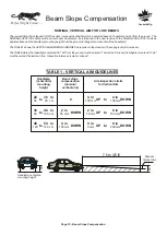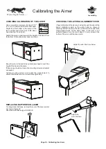
Position aimer at front of bay. Switch on laser by pushing button on laser housing. Measure center of laser beam height from floor at front
wheel and at back wheel. The distance from the floor should be the same. If it is not, adjust floor slope knob until they are equal. See fig.
16 and fig. 19. The laser has a built in timer and turns off automatically.
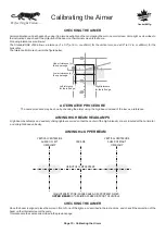
Calibrating the Floor
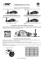
Floor compensation is required.
Vehicle and aimer are both located on a flat and level floor.
INITIAL FLOOR SLOPE COMPENSATION
Vehicle and aimer are both located on a flat floor with a
constant slope.
Floor compensation is required.
Vehicle and aimer are located on different flats, both of them
with a constant slope.
Floor compensation is required.
Vehicle and/or aimer are located on irregular flats.
It is recommended not to aim the headlamps on such
floors.
LASER GUIDED FLOOR SLOPE COMPENSATION SYSTEM
CAUTION
AVOID EXPOSURE - LASER LIGHT
IS EMITTED FROM THIS APERTURE
LASER RADIATION
DO NOT STARE
INTO BEAM
POWER OUTPUT < 1mW
WAVELENGHT: 630-680 nm
CLASS II LASER PRODUCT
fig. 16
RECORDING THE FLOOR SLOPE SETTING
Floor slope adjustment knob
9
8
7
6
5
4
3
2
1
…
†
fig. 19
Near the floor slope adjustment knob , there is a register consisting of a small cylinder that can be used to count the turns of the knob .
…
…
This register sinks or raises with each turn of the knob (fig. 19).
Shops using the aimer in more than one location should record the floor slope settings for each location.
ONCE THE SETTING IS RECORDED, IT IS NOT NECESSARY TO TAKE THE FLOOR SLOPE MEASUREMENT AGAIN FOR THIS
LOCATION.
Use the recorded floor slope setting for subsequent uses in the same location. Simply set the slope adjustment knob to the previously
recorded position prior to aiming headlights.
Bay No.
Register
Knob
Page 4 - Calibrating the Floor
Record floor slope information here for future reference.
Canbuilt Mfg.
Perfect Night Vision.....
Содержание OPT-5405
Страница 18: ......
Страница 20: ...NOTES...


