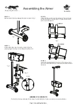
Page 2 - Assembling the Aimer
3
5
1
2
7
4
10
6
9
11
8
Assembling the Aimer
1
. Optical aimer head
2
. Heavy-duty mast
3
. Reinforced base with wheels
4
. Hardware to attach the mast to the base:
1 Bolt DIN 912, M 10 x 60
1 Washer DIN 7980, 10 mm
1 Flat washer, 10 mm
5
. Lateral alignment visor
6
. Lock / unlock mechanism
7. Mast cap
8. Precision floor slope compensation system
9. Aimer positioning system
10. Floor slope register
11. Laser guided floor slope measurement system (not shown)
COMPONENTS
B
B
A
fig. 7 pointer system
fig. 8
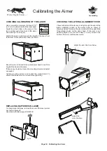
Attach the holder to the middle of
the aimer head, at the tip of the
pointer.
fig. 6
Hardware for Pointer
Positioning System
Install the pointer positioning system using hardware as
shown in fig. 7.
Hardware is attached to the optical aimer head and must be
removed for pointer installation fig.6.
STEP 1
Insert knob A through washer B,eye in pointer system and hen
insert another washer B.
Install assembly on optical aimer head tightening knob A
against aimer as shown in figure 7.
Canbuilt Mfg.
Perfect Night Vision.....
Содержание OPT-5405
Страница 18: ......
Страница 20: ...NOTES...


