


2
1.4
CHECKING EQUIPMENT
Check for signs of shipping damage upon receiving
equipment. Pay particular attention to parts accompanying
the boiler, which may show signs of being hit or otherwise
being mishandled. Verify total number of pieces shown on
packing slip with those actually received. In case there is
damage or a shortage, immediately notify carrier.
Figure 3: Checking the DynaFlame®
Do not attempt to pry any panel off. To begin disassembly
you must first remove the two ¼” bolts from the top of the
lid. Only then will you be able to remove the lid and
disassemble the three outer panels.
Once you have removed the lid carefully check and confirm
that all ¼” copper tubing connections are intact and have
not broken or loosened in shipment. Leaks at any
connections on these lines will result in erratic appliance
operation.
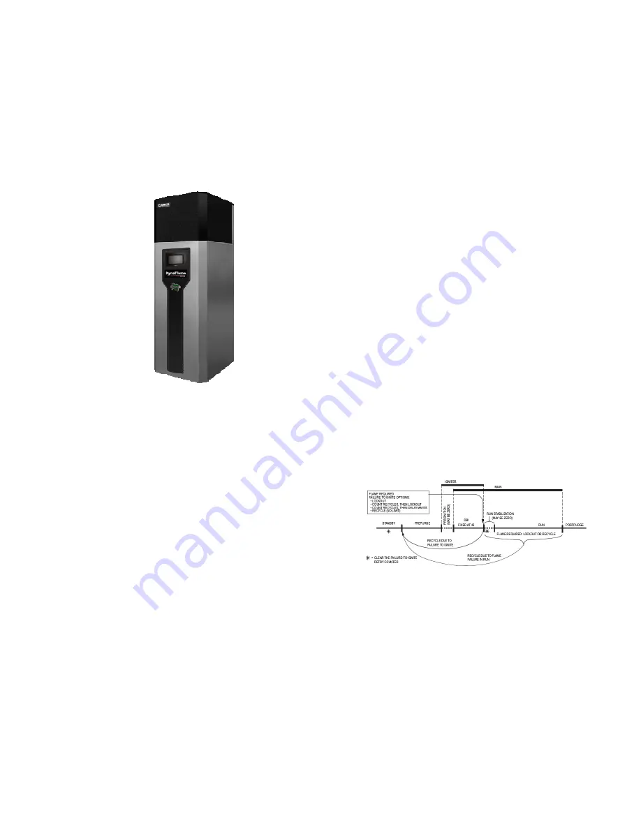
1.5
HOW IT OPERATES (SEQUENCE OF
OPERATION)
1
Supply power connection as per table 10.
2
The power switch is placed in the “ON” position.
3
120 VAC power is supplied to the control transformer.
4
24 VAC is supplied to the ignition module and low
voltage controls for all models.
5
After the appliance water pump starts, flow is proven
by the flow switch. The flow switch is to be mounted in
a tee at the outlet of the appliance. Take care to
properly trim the flow switch paddles so as not to jam
the switch in the tee. The normally open dry contacts in
the low water cutoff (LWCO) are to be wired in series
with the normally open contacts of the flow switch.
Locate the probe type LWCO in the piping above the
boiler inlet/outlet connection. The low water cutoff and
flow switch are shipped loose. In all cases check with
local codes.
6
The DynaFlame® controller receives a call for heat via
the remote operator contacts and the Demand
parameter reads Central Heating or DHW.
7
The local thermostat energizes the motor stop/start
relay which closes the initiate contacts to the variable
frequency drive (VFD) which starts to ramp up the
frequency to the 230V 3 phase motor of the
combustion fan. If the VFD is not in fault mode the
frequency will accelerate at the preprogrammed rate
towards maximum speed using the modulating signal
provided by the on board modulating control or the
remote operating system.
8
If temperature high limit, water flow and airflow
switches are closed the fan will run at pre-purge speed
until the pre-purge timer is satisfied. Once complete
the DynaFlame® will target the ignition fan speed.
9
DF 500 – DF 2500 (Direct Ignition): The hot surface
igniter will be energized for 22 seconds followed by
energizing the main valve for 4 seconds. A signal of
0.8dVdc must be recognized by the controller at the
flame sensor to keep the main gas valve in an open
position. The fan is kept at ignition speed until the
stabilization timer is satisfied.
DF 3000 – DF 5000 (Proven Pilot): The DynaFlame®
controller will activate the hot surface igniter for 22
seconds followed by powering the pilot valve for 10
seconds, whereupon a signal of 0.8Vdc must be
recognized by the controller at the flame sensor to
keep the main gas valve in an open position. The fan is
kept at ignition speed until the stabilization timer is
satisfied.
10 If the flame signal is not reached the module will stop
the ignition sequence after the trial for ignition.
11 The fan speed will slowly decrease as the heat request
nears the heat demand. The modulation rate is
controlled via a 4-20mA signal. If the heat demand is
sustained for a long duration of time the boiler will get
to a point of steady-state and the fan will rotate at
constant speed.
12 When the heat demand is satisfied or is removed the
burner will shut off and the fan speed will ramp up to
the preset Post-Purge speed until the Post-Purge timer
is satisfied.
13 The pump continues to circulate until the post-purge
time is satisfied.
14 The boiler will then go into Standby as it waits for the
next heat demand.
Note:
1. If a flame signal is detected at the end of the pre-purge
period an error statement to that effect will appear.
2. If at the end of the safety period (6 sec) no flame is
detected the control will go to post-purge to remove the
unburned gas. After this, a re-ignition attempt is started
following the same cycle. The number of re-ignition
attempts is limited to 2 after which a lockout occurs.
3. The burner can only be on continuously for a period of
24 hours. After this the burner is switched off and a
restart sequence follows.
4. The hot surface igniter is de-energized at the end of
the ignition period to allow for ionisation detection.
Содержание DFH/W1100
Страница 2: ......
Страница 40: ...35...
Страница 71: ...66 PART 12 EXPLODED VIEW...
Страница 72: ...67 3 44 10 45 46 47 28 31 26 52 57 58 59 54 60 61 SOLA Control Panel 39 4...
Страница 82: ...77 PART 13 ELECTRICAL DIAGRAMS...
Страница 83: ...78...
Страница 85: ...80...
Страница 86: ...81...
Страница 87: ...82...


