


60
PART 10 MAINTENANCE
CAUTION
It is important that all gas appliances to be serviced by a
Camus® trained service technician. It is in your own
interest and that of safety to ensure that all local codes,
and all the “NOTES” and “WARNINGS” in this manual are
complied with. To service or adjust this appliance, it is
imperative that the Camus® trained service technician
utilize a combustion analyzer to read CO
2
, CO and flue
pressure according to Camus® Hydronics recommendation
CAUTION
Label all wires prior to disconnection when servicing
controls. Wiring errors can cause improper and dangerous
operation
Listed below are items that must be checked to ensure safe
reliable operations. Verify proper operation after servicing.
10.1
EXAMINE THE VENTING SYSTEM
Examine the venting system at least once a year. Check
more often in the first year to determine inspection interval.
Check all joints and pipe connections for tightness,
corrosion or deterioration. Flush the condensate drain hose
with water to clean. Clean screens in the venting air intake
system as required. Have the entire system, including the
venting system, periodically inspected by a qualified service
agency.
10.2
VISUALLY CHECK MAIN BURNER
FLAMES
At each start up after long shutdown periods or at least
every six months. A burner view port is located on the
burner mounting flange.
CAUTION
The area around the burner view port is hot and direct
contact could result in burns
NOTE
Check torque on fan mounting nuts using a torque wrench.
Evenly tighten the nuts to 20 ft-lbs. Carefully examine the
area adjacent to the fan flange for signs of overheating
which are an indication that gaskets are in need of
replacement
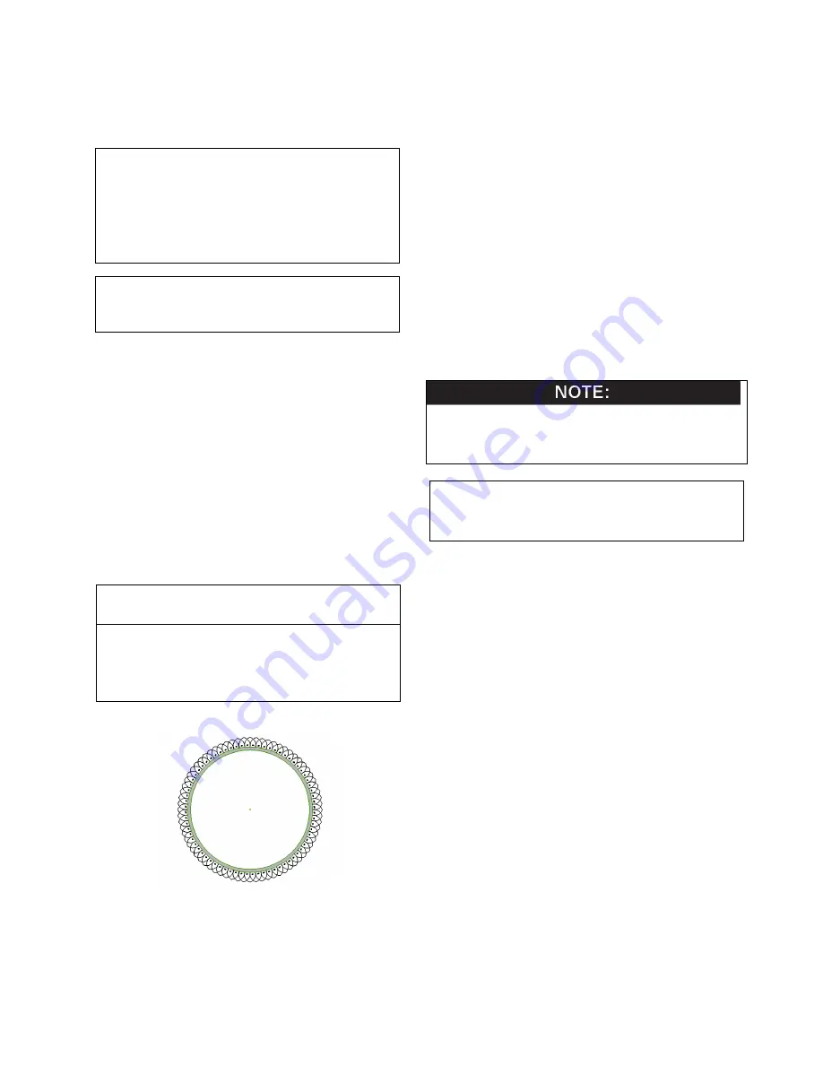
Figure 38: Normal Burner Flame Profile (short
dense and blue)
•
Normal Flame: A normal flame at 100% of burner input
is blue, with slight yellow tips a well defined flame and
no flame lifting.
•
Yellow Tip: Yellow tipping can be caused by blockage
or partial obstruction of air flow to the burner.
•
Yellow Flames: Yellow flames can be caused by
blockage of primary air flow to the burner or excessive
gas input. This condition MUST be corrected
immediately.
•
Lifting Flames: Lifting flames can be caused by over
firing the burner, excessive primary air or high draft in
excess of negative 0.15” W.C.
If improper flame is observed, examine the venting system;
ensure proper gas supply and adequate supply of
combustion and ventilation air.
10.3
FLUE GAS PASSAGEWAYS CLEANING
PROCEDURES
Any sign of soot around the inner jacket, outer jacket, flue
pipe connections, burner or in the areas between the fins
on the copper heat exchanger indicates a need for
cleaning. The following cleaning procedure must only be
performed by a qualified serviceman or installer. Proper
service is required to maintain safe operation. Properly
installed and adjusted units seldom need flue cleaning.
All gaskets/sealant on disassembled components or jacket
panels must be replaced with new gaskets/sealant on re-
assembly. Gasket and sealant kits are available from the
factory
CAUTION
When the vent system is disconnected for any reason it must
be
reassembled
and
resealed
according
to
vent
manufacturer’s instruction
10.4
CONDENSATION TREATMENT
This high efficiency appliance may operate as a condensing
appliance for extended periods of time based on return
water temperatures. Condensate occurs when the products
of combustion are cooled below their dew point in the heat
transfer process. The liquid condensate formed from this
high efficiency heat transfer process is mildly acidic. The
condensate will typically have a pH ranging from 4.0 to 5.0
as it is discharged from the condensate drain at the rear of
the appliance. The internal jacket area where the
condensate is collected (CHRM) is constructed from a
special corrosion resistant stainless steel. All materials
external to the appliance in contact with the condensate
must be corrosion resistant. This is typically accomplished
by using PVC or CPVC plastic pipe and synthetic tubing.
Condensate must be able to flow freely from the appliance.
All condensate flow is accomplished by gravity requiring a
minimum downward slope of 1/4” per foot (21mm/m) to
ensure proper flow to the condensate management system
and/or a suitable drain. The neutralizer MUST always be
mounted on the same level or lower than the bottom of the
appliance cabinet and downstream of the condensate trap.
All condensate piping and connections must be easily
accessible for routine maintenance and inspection.
10.4.1
CONDENSATE VOLUME
There are several factors affecting the amount of
condensation created by the appliance CHRM, however for
rough approximation use.
Condensation Volume, US Gallon/Hr = Input, MBH/1000 x
Содержание DFH/W1100
Страница 2: ......
Страница 40: ...35...
Страница 71: ...66 PART 12 EXPLODED VIEW...
Страница 72: ...67 3 44 10 45 46 47 28 31 26 52 57 58 59 54 60 61 SOLA Control Panel 39 4...
Страница 82: ...77 PART 13 ELECTRICAL DIAGRAMS...
Страница 83: ...78...
Страница 85: ...80...
Страница 86: ...81...
Страница 87: ...82...


