background image


CS110 

Electric Field 

Meter 


 Instruction Manual 


 Issued: 29.5.12


Copyright 

©

 2005-2012 Campbell Scientific Inc. 

  Printed under Licence by Campbell Scientific Ltd. 


CSL 619 

Содержание CS110

Страница 1: ...CS110 Electric Field Meter Instruction Manual Issued 29 5 12 Copyright 2005 2012 Campbell Scientific Inc Printed under Licence by Campbell Scientific Ltd CSL 619 ...

Страница 2: ......

Страница 3: ...110 CAMPBELL SCIENTIFIC LTD does not warrant that the CS110 will meet customer s requirements or that its operation will be uninterrupted or error free Atmospheric or local electric field conditions or different site characteristics may cause false information late data or otherwise incomplete or inaccurate data The CS110 only measures conditions that make lightning more likely Just as with weathe...

Страница 4: ......

Страница 5: ...al cell phones and aerials may also not be applicable according to your locality Some brackets shields and enclosure options including wiring are not sold as standard items in the European market in some cases alternatives are offered Details of the alternatives will be covered in separate manuals Part numbers prefixed with a symbol are special order parts for use with non EU variants or for speci...

Страница 6: ......

Страница 7: ...quirements 8 4 2 Campbell Scientific Inc Power Supplies 9 4 3 Communication Options 9 4 4 Site Recommendations 10 5 Factory Calibration and Site Correction 10 5 1 Factory Calibration 10 5 2 Site Correction 13 6 Lightning Warning 17 7 CRBasic Programming 19 8 CS110 Measurement Instructions 22 8 1 CR1000 Measurement Overview 22 8 2 Measuring Electric Field 24 8 3 Measuring Electric Field Change 24 8...

Страница 8: ... C CS110 Connector Pin outs C 1 D Servicing the CS110 D 1 D 1 Lid Gasket D 1 D 2 Changing Out the CR1000 D 1 D 3 Changing Out Motor Assembly D 2 D 4 Changing Out the CS110 Panel Board Assembly D 2 D 5 Shutter Encoder Alignment D 2 D 6 Motor O ring Seal D 6 E CS110 as a Slow Antenna E 1 E 1 Response of the CS110 Slow Antenna in the Frequency Domain E 1 E 2 Response of the CS110 Slow Antenna in the ...

Страница 9: ...Metre CM10 Tripod Site 16 12 Electric Field Measured with CS110 During Local Thunderstorm 18 13 CS110 Stator Shutter and Sense Electrode 32 14 Inside of CS110 Case Illustrating Bracket for Holding Desiccant 34 D 1 Exploded View of CS110 Electric Field Meter D 1 D 2 CS110 Motor Assembly D 4 E 1 CS110 slow antenna frequency response E 2 E 2 KSC electric field and CS110 slow antenna data E 3 E 3 KSC ...

Страница 10: ...iv This is a blank page ...

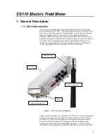
Страница 11: ...e amplifiers converts the modulated charge into AC voltages that are synchronously rectified and filtered to form a low frequency voltage proportional to the low frequency 10 Hz electric field Figure 1 CS110 Electric Field Meter Unlike traditional rotating vane field mills the CS110 uses a reciprocating shutter A stepper motor opens and then closes the reciprocating shutter by 45 during measuremen...

Страница 12: ...ic pressure sensors interface directly to the CS110 Measurement details of the various sensors are given in section 7 1 4 Communication and Data Storage The circular RS 232 connector on the underside of the CS110 can be used to interface directly to RS 232 devices DTE or DCE utilizing the CS110 RS 232 cable CS110CBL1 The circular CS I O connector on the underside of the CS110 can be used to interf...

Страница 13: ... returned from each electric field measurement reports on instrument health along with any measurement problems as described in Appendix A For example insulator leakage current is measured during each electric field measurement indicating the cleanliness of electrode insulators A leakage current compensation circuit for the charge amplifier input is incorporated in the CS110 to minimize the effect...

Страница 14: ...ield enhancement due to typical inverted and elevated mounting requires additional site correction estimated at 5 accuracy when done in appropriate high field conditions Practical outdoor CS110 electric field measurement accuracy is estimated at 5 of reading 8 V m 1 for the CS110 2 metre CM10 Tripod Site 3 The CS110 incorporates automatic gain ranging between two input ranges The measurement is fi...

Страница 15: ...S100 barometer or CS106 barometer Rain CS700 TB4 TE525 TE525WS TE525MM 1 One sensor per connector Programmability CRBasicTM programming allows the selection of sample rate data processing and storage options and setting output ports based on alarm conditions LoggerNetTM includes the CRBasic editor and compiler Rugged Construction Ultra reliable metallic ground connection to reciprocating shutter n...

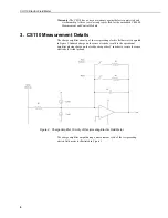
Страница 16: ...ier circuitry of the reciprocating electric field meter is depicted in Figure 2 Induced charge on the sense electrode results in the operational amplifier placing charge on the feedback capacitor C in order to restore the sense electrode to virtual ground Figure 2 Charge Amplifier Circuitry of Reciprocating Electric Field Meter The charge amplifier output during a measurement cycle of the reciproc...

Страница 17: ...between zero field reference measurements which is approximately 140 ms Measurement noise due to 50 or 60 Hz AC power can be suppressed by utilizing the 50 Hz or 60 Hz noise rejection measurement capability of the datalogger Current source Ileak in Figure 2 represents leakage currents across the Teflon insulators supporting the sense electrode along with the input bias current of the operational a...

Страница 18: ...ments using the 250 μs integration duration for an analogue integrator result in an upper 3 dB bandwidth of 1 8 kHz Detailed information regarding the slow antenna mode of the CS110 is given in Appendix E and Section 8 3 4 Site Requirements and Recommendations 4 1 Power Requirements Field mills typically consume many watts of power because their motors are operated continuously In the reciprocatin...

Страница 19: ... CS110 and peripherals Larger capacity battery packs are also available such as the PS17E LA The rechargeable battery can be trickle charged from an ac power wall charger Charging power can also come from a 17 28 VDC input such as a solar panel Depending on power requirements 10 watt or 20 watt solar panels are available 4 3 Communication Options The circular RS 232 connector on the underside of t...

Страница 20: ...ation LPLWS Roof mounted electric field measurements are practical if a site correction can be done to account for field distortions Also a good Earth ground connection to the CS110 and associated mounting hardware is necessary to make a given site appear as a vertical extension of the Earth ground It is recommended that the integrity of this Earth Ground connection be checked periodically by veri...

Страница 21: ...ions in surface cleanliness along with charging and discharging processes Polished 316 L stainless steel is used for critical electrode surfaces on the CS110 to minimize unwanted surface charges CS110s with clean electrodes have been found to display electric field offsets 30 V m which has negligible effect on the determination of Mparallel_plate because of the 15 kV m range of electric fields use...

Страница 22: ...ata for a typical CS110 factory calibration and resulting determination of Mparallel_plate 84 32 V m mV Volts metre millivolt is illustrated in Figure 6 y 84 324x 26 258 R2 1 20000 15000 10000 5000 0 5000 10000 15000 20000 200 150 100 50 0 50 100 150 200 250 Charge Amplifier Output Voltage mV Applied Electric Field V m Figure 6 Factory Calibration Data for CS110 SN 1026 ...

Страница 23: ...tioned each CS110 is factory calibrated in a parallel plate calibration fixture resulting in calibration equation 4 However when monitoring the Earth s electric field equation 4 is valid only if the instrument aperture is mounted flush with the Earth s surface and upward facing Yet for permanent outdoor measurements of electric field a flush mounted and upward facing orientation is problematic bec...

Страница 24: ...llel_plate for non flush mounted configurations McGorman and Rust The corrected multiplier Mcorrected becomes as follows Mcorrected Csite Mparallel_plate Eq 5 In equation 5 Mparallel_plate is unique for each CS110 yet independent of a given site whereas Csite is unique for each given site yet independent of the particular CS110 used at the site Csite is typically determined by using a flush mounte...

Страница 25: ...c Field Meter Site Correction Facility An upward facing calibration kit PN 01034 was developed to hold the CS110 in a flush mounted upward facing position as illustrated in Figure 10 Figure 10 CS110 Attached to Upward Facing Flush Mounted Plate for Site Correction ...

Страница 26: ... Scientific Ltd has performed a site correction on the CS110 2 Metre CM10 Tripod Site described in Appendix G The collected data between the upward facing unit and a downward facing CS110 2 Metre CM10 Tripod site is illustrated in Fig 11 A best fit line computed from the data resulted in Csite 0 105 4 which is valid for users at other sites who use the same site dimensions on level terrain clear o...

Страница 27: ... the presence of nearby electrified clouds capable of producing lightning discharges Consequently electric field monitors can give warning at the beginning of storms prior to hazardous discharges Both lightning detectors and electric field monitors are employed in high risk applications Lightning safety guidelines based on human observations exist and should not be ignored simply because of the pr...

Страница 28: ...s that have been used are 1000 V m LPLWS and 2000 V m NAVSEA Obviously the lower the level used the more risk reduction available at the expense of increased down time for operations suspended for lightning hazard warning Campbell Scientific is not liable for the reliability and performance of the warning algorithms implemented by users of our equipment While lightning warning systems can greatly ...

Страница 29: ...anel_temp ieee4 0 Average panel temperature over interval Average 1 internal_RH ieee4 0 Average internal case RH Average 1 battery_volt ieee4 0 Use 4 byte ieee4 format for wide dynamic range Average 1 E_field ieee4 0 StdDev 1 E_field ieee4 0 Average 1 leakage_cur ieee4 0 Maximum 1 status ieee4 0 False EndTable BeginProg Scan 1 sec 0 0 Scan loop occurring every second PanelTemp panel_temp 250 Measu...

Страница 30: ...to the output processing instructions associated with a given table A more involved program that incorporates site correction multiplier rainfall wind speed and direction solar radiation relative humidity and air temperature along with electric field follows CS110 efield and weather station program CS110_WStation cr1 Measures rainfall wind speed and direction solar radiation relative humidity and ...

Страница 31: ...ror_Count NAN Then Error_Count 0 EndIf Scan 1 sec 0 0 for k 1 to 16 Initialize status array E_status k 0 next PanelTemp panel_temp 250 Battery battery_volt VoltDiff internal_RH 1 mV2500 5 True 0 250 0 1 0 PulseCount rain_fall 1 2 2 0 0 01 0 TE525 tipping bucket 0 01 inches per tip PulseCount wind_speed 1 1 1 1 0 2192 0 Mult for 05103 Wind Monitor BrHalf wind_dir 1 mV2500 4 Vx2 1 2500 False 450 250...

Страница 32: ...essing instruction such as Average This can be conveniently accomplished using a disable variable DisableVar associated with appropriate output processing instructions The last parameter of the Average instruction is the DisableVar and will exclude the current measured value when DisableVar is not equal to zero In order to prevent a single NAN electric field result from corrupting measurements ove...

Страница 33: ...d in single ended measurements by measuring the voltage on the internal ground reference The MeasOff parameter in the VoltSe instruction determines if this internal ground reference is measured at the beginning of every VoltSe instruction MeasOff True or whether a single ended offset voltage measure is performed as part of an on going instrument self calibration routine occurring in background Mea...

Страница 34: ...s for _50Hz and _60Hz are 20 ms and 16 67 ms respectively for cancellation of unwanted 50 Hz and 60 Hz noise Mult provides for convenient scaling within the measurement instruction and Offset provides for convenient incorporation of offsets The CS110 instruction measures the electric field utilizing the 250 mV range If the result is NAN the instruction re measures utilizing the 2500 mV input volta...

Страница 35: ...high Scan 1 Sec 0 0 If Iftime 3599 3600 sec then PortSet 4 1 VoltDiff Barom_pres 1 mV2500 3 True 450 250 0 2 600 If Iftime 0 3600 sec then PortSet 4 0 NextScan 8 5 Measuring Air Temperature and Relative Humidity Circular connector labelled TEMP RH can be used to connect up an HC2S3 temperature and relative humidity sensor Example CRBasic instructions to measure the HC2S3 Temperature and RH are giv...

Страница 36: ...munication options e g phone to RF PakBus routing or scheduled data collection LoggerNet software is recommended for applications that require these capabilities The CS110 s embedded CR1000 datalogger is only supported in LoggerNet version 3 0 and higher or PC400 version 1 0 and higher Upgrades to earlier versions of LoggerNet or PC208W are available for approximately half the list price The follo...

Страница 37: ...Instruction Manual 27 ...

Страница 38: ...it has been executed Once this is done switch to the Connect button on the LoggerNet Tool Bar select the CS110 and select Connect If the connection is made and the stations time shows up in the window you can then select the Numeric button and add the desired public variables to see electric field readings updated every measurement interval ...

Страница 39: ...d Device Configuration Utility that will discover the PakBus address Run the software and set it up with device type set to CR1000 specify the correct COM port and select Connect and the software will discover the PakBus address for you If necessary this software is also used to send a new operating system OS to the CR1000 The following screen captures show the Device Configuration software ...

Страница 40: ...r web site NO OX ID A SPECIAL is a soft wax based rust preventive and lubricant that contains an active rust inhibitor and small amount of solvent for ease of application This corrosion resistant coating can be applied by spray or brush application NO OX ID A SPECIAL controls corrosion by leaving a thick semi transparent non drying barrier coating that retains its anti rust properties indefinitely...

Страница 41: ...n high heat environments up to 1600 F Prevents rust corrosion seizing and eases disassembly Reduces friction and wear to critical parts Buttery texture ideal for both coarse and fine threads Exceptional lubrication properties Typical Applications For use with copper brass cast iron and all alloys including stainless steel all plastics and all non metallic gasket materials Bolts bushings pipes fitt...

Страница 42: ... status values are described in Appendix A The leakage parameter returns the measured charge amplifier input leakage current A perfect unit is 0 nA Actual units deviate from perfection such that some have small 1 nA positive leakage current and some have small negative leakage current Occasional leakage current values exceeding 4 2 nA may occur if insulators are wet If leakage current values retur...

Страница 43: ...ch deposits off with soap and hot water if available Any residue may form non conductive layers that can hold unwanted surface charge Using a brush that will fit between the shutter and the sense electrode carefully wash the shutter and sense electrode along with the three insulators attaching the sense electrode to the main body of the CS110 One brush CSI PN 17578 ships with each CS110 Large offs...

Страница 44: ...Inside of CS110 Case Illustrating Bracket for Holding Desiccant Replacement intervals less than once every six months for the 4 Unit PN 005669 desiccant pack within the sealed CS110 case indicate a problem with the CS110 case seal or with the desiccant packs being used Procedure for Changing Desiccant 1 Remove the CS110 case lid by unscrewing the captive screws that attach the lid to the main body...

Страница 45: ...the 1 8 stepper motor step size on both edges of each of the 4 openings in the stator when viewed from a perpendicular position to the direction of the shutter blades No visible gaps between the stator and shutter blades should be visible on a fully closed shutter when viewed from a position perpendicular to the shutter blades Program to open close the CS110 shutter CS110_Shutter1 cr1 Last updated...

Страница 46: ...y better than 10 a parallel plate factory calibration is recommended every three years The expected lifetime of the CS110 is 5 to 10 years again depending upon the operational environment Instruments operated in coastal environments will likely suffer from external finish degradation and or operational failure sooner than instruments operated in dry inland environments 11 References Lightning Phys...

Страница 47: ... years again depending upon the operational environment Instruments operated in coastal environments will likely suffer from external finish degradation and or operational failure sooner than instruments operated in dry inland environments 11 References Lightning Physics and Effects by Vladimir A Rakov and Martin A Uman Cambridge University Press 2003 The Electrical Nature of Storms by Donald R Ma...

Страница 48: ......

Страница 49: ... through 6 are common upon power up or if the shutter has been touched or bumped since the last execution of the CS110 instruction Persisting status codes 4 through 6 indicate a problem with parking the shutter that should be investigated Status codes 7 through 10 Datalogger warnings and errors status 7 5Vext low Return measured Efield value status 8 Datalogger skipped scan Return measured Efield ...

Страница 50: ...oder DNCNTs 24 or 26 or don t find home when closing Return NAN instead of measured Efield value status 16 Can t properly position shutter Return NAN instead of measured Efield value Status code 11 returns the measured Efield value because the electric field computation algorithm compensates for leakage current even if it exceeds 4 2 nA although maximum signal amplitude becomes limited Consequentl...

Страница 51: ...esulting in a valid calibration for a flush mounted upward facing configuration Yet inverted and elevated CS110 mounting configurations are recommended for long term installations Upward facing site calibration kit PN 01034 has been designed to provide a flush mounted upward facing configuration for the CS110 to aid in determining site correction factors B 3 CR1000 Keyboard Display The CR1000 keyb...

Страница 52: ...Appendix B CS110 Accessories This is a blank page B 2 ...

Страница 53: ...1 3 2 6 4 5 1 4 2 9 5 7 3 8 6 POWER CONNECTOR CS110CBL3 L CS110 Power Cable Connector is female and is CSI PN 17654 Conxall 6282 6SG 522 or Switchcraft EN3C6F Pin 1 is indicated with a dot Pin Description Colour 1 C1 Control Port 1 Blue 2 12 V Power Red 3 Gnd Digital Ground Drain clear 4 P_Gnd Power Ground Black 5 C3 Control Port 3 Green 6 C2 Control Port 2 Yellow WIND CONNECTOR Connector is male ...

Страница 54: ... Conxall 3082 9SG 330 Pin 1 is indicated w a dot Pin Description 1 5V 5 Volt dc supply 2 Gnd Power ground 3 Ring Ring 4 RX Receive 5 ME Modem enable 6 SDE Synchronous device enable 7 CLKHS Clock hand shake 8 12V 12 Volt dc supply 9 TX Transmit RS 232 CONNECTOR CS110CBL1 L CS110 RS 232 Cable Connector is 9 pin male and is CSI PN 15880 Conxall 3282 9PG 330 Pin 1 is indicated w a dot Pin Description ...

Страница 55: ...channel 3 3 12V 12 Volt dc supply 4 C4 Control port 4 5 C3 Control port 3 6 Gnd Power ground TEMP RH CONNECTOR Connector is male and is CSI PN 9889 Conxall 6282 6PG 522 or Switchcraft EN3C6M Pin 1 is indicated w a dot Pin Description 1 1HI Single ended channel 1 or high side of differential channel 1 2 1LO Single ended channel 2 or low side of differential channel 1 2 1Kohm Pin 2 also connects to ...

Страница 56: ...Appendix C CS110 Connector Pin outs C 4 This is a blank page ...

Страница 57: ...he CR1000 The CR1000 datalogger is accessible in the CS110 by removing the case lid The CR1000 is secured to the CS110 via the desiccant holder bracket along with the two thumb screws on the CR1000 module Light prying on the CR1000 module is required to unplug the three 40 pin connectors that interface to the CS110 panel board after removing the two thumb screws on the CR1000 module When installin...

Страница 58: ...cket along with the two thumb screw on the CR1000 module Next remove the black anodized interface plate between the CR1000 and CS110 panel board Next remove the mounting posts that support the black anodized interface plate followed by the two Phillips head screws by the motor assembly that attach the CS110 panel board PCB to the CS110 case Disconnect the three locking electrical connectors that c...

Страница 59: ...el_Temp BeginProg Scan 10 msec 0 0 If Flag 1 Then CS110Trim 1 Take a step open Flag 1 0 Reset Flag 1 EndIf If Flag 2 Then CS110Trim 1 Take a step closed Flag 2 0 Reset Flag 2 EndIf If Flag 3 Then Exit scan via Flag 3 Flag 3 0 ExitScan EndIf NextScan Scan 1000 msec 0 0 For I 1 To 25 Loop to fully close a fully opened shutter CS110Trim 1 Take a step closed Delay 0 10 mSec Next I ExitScan NextScan Sc...

Страница 60: ...e 4 openings in the stator Once the shutter has been adjusted to the fully open position by means of flags 1 and 2 flag 3 is to be set high to execute a 25 closed step loop which positions the shutter in the fully closed position which is the desired position for the Index trim No visible gaps between the stator and shutter blades should be visible in the fully closed shutter position Once in the ...

Страница 61: ...ram can be used to verify proper opening and closing of the shutter Stator to shutter overlap exists in the fully opened and fully closed positions so that slight shutter position variations do not alter the exposed area to the sense electrode A fully opened shutter will display symmetrical stator to shutter overlap within the 1 8 stepper motor step size on both edges of each of the 4 openings in ...

Страница 62: ...otor O ring the CS110 shutter is installed to compress the O ring When replacing the shutter line up the set screw hole so that it is perpendicular to the flat surface on the motor shaft The shutter should then be compressed by applying a precise force Campbell Scientific part number 010345 is used to apply the precise force A second shutter hub set screw is used to prevent the primary shutter hub...

Страница 63: ...tion of the CS110Shutter instruction with the open command changes the CS110 panel board charge amplifier circuitry to a slow antenna by switching in a 200 MΩ resistor in parallel with the 330 pF feedback capacitor resulting in a 330pF 200MΩ 66 ms decay time constant In this slow antenna configuration the charge amplifier has a high pass filter frequency response with the lower cut off frequency d...

Страница 64: ...10 100 1 10 3 1 10 4 0 0 167 0 333 0 5 0 667 0 833 1 Overall Frequency Response of CS110 Slow Antenna Measurement with 250 us Integration Frequency Hz Relative Magnitude 0 999 0 MagSys f 10000 0 1 f Figure E 1 CS110 slow antenna frequency response ...

Страница 65: ...lowing graphs shows one lightning strike measured at 50 Hz by both the CS110 slow antenna and by one of Kennedy Space Centre s KSC field mills In Figure E 3 the KSC electric field meter readings have been converted to efield change per measurement Figure E 2 KSC electric field and CS110 slow antenna data ...

Страница 66: ...g for some of the differences in the data shown in the above graph Since that time the CS110 has been improved and now has the ability to sync to within 10 µs of the GPS signal s PPS pulse The resolution of accuracy for the clock set is 10 microseconds if the internal CR1000 datalogger has a hardware revision number greater than 007 RevBoard field in the datalogger s Status table ...

Страница 67: ...ent compensation value and is only executed once The CS110Shutter instruction can fully open or fully close the shutter based on the whether the 2nd parameter is a 1 or 0 respectively Two VoltDiff instructions are used on two different input voltage ranges to provide more dynamic range in the charge amplifier output measurement The CS110 can be programmed to operate as a field meter and then switc...

Страница 68: ...is operating as a slow antenna Switching in the 200 MΩ resistor in the feedback path simply slows the decay of the signal induced on the sense electrode resulting in a 66 millisecond decay time constant The CS110 operating as a slow antenna returns the change in the electric field with units of volts per metre per scan A 50 Hz scan interval would yield X volts metre 1 20 ms 1 ...

Страница 69: ...er station site const Mcorrected Mparallel_plate Csite Mcorrected is multiplier for CS110 instruction const SLOW_INTERVAL 10 const FAST_INTERVAL 1 Public E_field Units E_field volts m Public battery_volt Public leakage_cur Units leakage_cur nA Public status Public panel_temp Units panel_temp DegF Public rain_fall Units rain_fall inch Public wind_speed Units wind_speed mph Public wind_dir Units win...

Страница 70: ...L Initialize to fast interval Scan 1 sec 0 0 for k 1 to 16 Initialize status array E_status k 0 next PanelTemp panel_temp 250 panel_temp panel_temp 1 8 32 Convert to Fahrenheit Battery battery_volt VoltDiff internal_RH 1 mV2500 5 True 0 250 0 1 0 PulseCount rain_fall 1 2 2 0 0 01 0 TE525 tipping bucket 0 01 inches per tip PulseCount wind_speed 1 1 1 1 0 2192 0 Mult for 05103 Wind Monitor BrHalf wi...

Страница 71: ...every time at slow interval NextScan EndProg In the above program all measurements except the electric field measurement are done once per second The electric field measurement is done once every SLOW_INTERVAL when measured electric field values are between 300 V m and 100 V m as determined by an if statement The 300 V m and 100 V m values are somewhat arbitrary and can easily be changed to better...

Страница 72: ...Appendix F Example CRBasic Programs This is a blank page F 4 ...

Страница 73: ...wing may affect the site calibration factor Csite CM10 Tripod CS110 Electric Field Meter ENC 12 14 Enclosure If the above items are installed using the following set of instructions the site is level with a 762 cm 25 foot radius of gravel around the tripod and there are no obstructions higher than 18 degrees from the centre of a measurement site2 then the Csite determined for this configuration sh...

Страница 74: ...removing or adding small amounts of gravel under the feet as needed Apply Teflon tape to both ends of the 3 175 cm 1 inch outside diameter mast Attach the cap to the top of the mast Attach the CS110 mounting bracket to the mast with the top of the bracket about 23 5 cm 9 inches below the top of the cap on the mast but don t tighten bolts very tight as it will likely need to be rotated and either r...

Страница 75: ...there is a solar panel install the solar panel on the leg facing the equator below the enclosure Tilt the solar panel at an angle less than horizontal that is equal to the latitude plus 10 degrees see solar panel manual Ground the CS110 Electric Field Meter Figure G 2 the tripod and the battery through the enclosure ground with three separate ground wires as shown in Figure G 3 Power and communica...

Страница 76: ... SN1022 with Mparallel_plate 87 6 Tripod with CS110 only SN1023 with Mparallel_plate 81 77 Each CS110 recorded one minute averages of 1 second measurements of electric field data for the same 2200 to 2300 hour time period on October 2 2005 The data from both units is plotted in Figure G 4 A best fit line was computed The linear regression yields a Csite 0 105 for the Tripod CS110 Only Site G 4 ...

Страница 77: ...8000 80000 60000 40000 20000 0 20000 40000 60000 80000 Uncorrected Csite 1 Electric Field volt meter for Tripod CS110 Only site SN 1023 Mparallel_Plate 81 77 volt meter millivolt Electric Field volt meter for Upward Facing CS110 SN 1022 Mparallel_plate 87 6 volt meter millivolt Tripod CS110 Only Uncorrected E_Field 1_Min_Avg volts m Linear Tripod CS110 Only Uncorrected E_Field 1_Min_Avg volts m FI...

Страница 78: ...Appendix G CS110 2 Metre CM10 Tripod Site This is a blank page G 6 ...

Страница 79: ...ite CM10 Tripod StrikeGuard Lightning Detector CS110 Electric Field Meter ENC 12 14 Enclosure If the above items are installed using the following set of instructions the site is level with a 25 foot radius of gravel around the tripod and there are no obstructions higher than 18 degrees from the centre of a measurement site2 then the Csite determined for this configuration should be valid H 1 ...

Страница 80: ... cm 1 inch outside diameter mast Attach the cap to the top end of the mast Attach the CS110 mounting bracket to the mast with the top of the bracket about 23 5 cm 9 inches below the top of the cap on the mast but don t tighten bolts very tight as it will likely need to be rotated and either raised or lowered slightly Mount the completed mast and cross arm on the tripod Adjust the CS110 mounting br...

Страница 81: ...o pull the hinge rivets out of the enclosure If there is a solar panel install the solar panel on the leg facing the equator below the enclosure Tilt the solar panel at an angle less than horizontal that is equal to the latitude plus 10 degrees see solar panel manual Ground the CS110 Electric Field Meter Figure H 3 the tripod and the battery through the enclosure ground with three separate ground ...

Страница 82: ... H Tripod CS110 and StrikeGuard Site FIGURE H 4 Grounding the Tripod and Battery Stake the tripod to the ground or weight it down with sand bags Connect power and communication cables as shown in Figure H 5 H 4 ...

Страница 83: ...eGuard Site FIGURE H 5 Connections for Combined System Power and communication cables should be run down the equator side of the mast and under the enclosure as shown Wire tie all cables into place so they don t move with the wind H 5 ...

Страница 84: ... a Csite 0 108 for the Tripod CS110 and StrikeGuard Site Site Correction for CS110 StrikeGuard on CM10 Tripod August 11 2005 1 minute average of 1 second samples Results indicate Csite 0 108 y 0 1079x 64 062 R 2 0 9994 4000 2000 0 2000 4000 6000 8000 10000 40000 20000 0 20000 40000 60000 80000 100000 Uncorrected Electric Field volts meter for CM10 tripod mounted StrikeGuard 2 Meter CS110 SN1023 Mp...

Страница 85: ......
Страница 86: ...berta T5M 1W7 CANADA www campbellsci ca dataloggers campbellsci ca Campbell Scientific Centro Caribe S A CSCC 300N Cementerio Edificio Breller Santo Domingo Heredia 40305 COSTA RICA www campbellsci cc info campbellsci cc Campbell Scientific Ltd CSL Campbell Park 80 Hathern Road Shepshed Loughborough LE12 9GX UNITED KINGDOM www campbellsci co uk sales campbellsci co uk Campbell Scientific Ltd Franc...

Отзывы: