


Appendix D. Servicing the CS110
D-2
proper connector orientation is verified, set the CR1000 into the CS110 case and
feel for proper positioning of the three 40-pin connectors. When the connector
shrouds are engaged, press down firmly on the CR1000 to mate the connector
pins, prior to engaging the two thumb screws on the CR1000 module. Replace
the desiccant holder bracket and desiccant after tightening the thumb screws.
D.3 Changing Out Motor Assembly
First remove the CR1000 by removing the desiccant holder bracket along with the
two thumb screws on the CR1000 module. Next remove the black anodized
interface plate between the CR1000 and CS110 panel board. Unplug the three
locking electrical connectors on the CS110 panel board from the motor assembly.
Remove the stator by loosening the 2 Philips head screws located on the
underside of the CS110. Next remove the four Philips head screws that attach the
motor assembly to the white powder-coated aluminium case. With the four
screws removed, carefully break it free from the bond to the gasket and allow it to
be removed through the bottom of the CS110 case. Be sure to check the integrity
of the motor assembly gasket on the CS110 case before replacing the motor
assembly.
Replacement of the motor assembly invalidates the factory
calibration of a CS110 because of possible dimensional differences
between assemblies.
D.4 Changing Out the CS110 Panel Board Assembly
First remove the CR1000 by removing the desiccant holder bracket along with the
two thumb screw on the CR1000 module. Next remove the black anodized
interface plate between the CR1000 and CS110 panel board.
Next remove the mounting posts that support the black anodized interface plate
followed by the two Phillips head screws by the motor assembly that attach the
CS110 panel board PCB to the CS110 case. Disconnect the three locking
electrical connectors that connect signals between the CS110 panel board and the
motor assembly. Next remove the plastic nuts from the circular connectors on the
outside of the CS110 case. The CS110 panel board should now be free and can
be manoeuvred out of the case.
Reverse the above procedure when installing a CS110 panel board PCB. Make
sure that the circular connectors each have a functional o-ring before placing the
CS110 panel board inside the CS110 case. The plastic nuts on the circular
connectors should be tightened to a torque of 10-12 inch
⋅
lbs.
Readers are referred to Section 10 on Maintenance for instructions on how to
clean the CS110 electrodes and change desiccant in the sealed CS110 case.
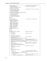
D.5 Shutter/Encoder Alignment
A factory trim is done to align the position of the CS110 shutter with an Index
mark on the rotary position encoder. Re-trimming of the shutter/encoder
alignment becomes necessary after encoder disassembly. The procedure to trim
the shutter/encoder alignment uses a CS110 single-step trim instruction called
CS110Trim
. This instruction allows a single shutter step open (flag 1) and
closed (flag 2) utilizing the flag capability in LoggerNet. The following CS110
program listing (CS110_Index_Trim.cr1) is for trimming the Index mark to the
fully closed shutter position.
NOTE
Содержание CS110
Страница 2: ......
Страница 4: ......
Страница 6: ......
Страница 10: ...iv This is a blank page ...
Страница 37: ...Instruction Manual 27 ...
Страница 48: ......
Страница 52: ...Appendix B CS110 Accessories This is a blank page B 2 ...
Страница 56: ...Appendix C CS110 Connector Pin outs C 4 This is a blank page ...
Страница 72: ...Appendix F Example CRBasic Programs This is a blank page F 4 ...
Страница 78: ...Appendix G CS110 2 Metre CM10 Tripod Site This is a blank page G 6 ...
Страница 85: ......