


8. Click Wiring Diagram on the left side of the window to see how to wire the sensor to the
data logger. With the power disconnected from the data logger, insert the wires as directed
in the diagram. Ensure you clamp the terminal on the conductor, not the wire insulation.
Use the included flat-blade screwdriver to open/close the terminals.
9. Click Sensors on the left side of the window to return to the sensor selection window, then
click Next at the bottom of the window.
10. Type 1 in the How often should the data logger measure its sensor(s)? box.
11. Use the Output Setup options to specify how often measurements are to be made and how
often outputs are to be stored. Note that multiple output intervals can be specified, one for
each output table (Table1 and Table2 tabs). For the example program, only one table is
needed. Click the Table2 tab and click Delete Table.
12. In the Table Name box, type a name for the table. For example: OneMin.
13. Select a Data Output Storage Interval. For example: to 1 minute.
14. Click Next.
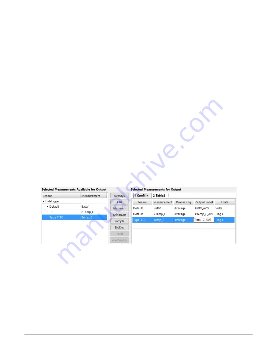
15. Select the measurement from the Selected Measurements Available for Output list, then
click an output processing option to add the measurement to the Selected Measurements
for Output list. For the example program, select BattV and click the Average button to add
it to the Selected Measurements for Output list. Repeat this procedure for PTemp_C and
Temp_C.
16. Click Finish and give the program a meaningful name such as a site identifier. Click Save.
17. If LoggerNet or other data logger support software is running on your computer, and the
data logger is connected to the computer (see
Making the software connection
(p. 43) for
more information), you can choose to send the program. Generally it is best to collect data
first; so, we recommend sending the program using the instructions in
3. Setting up the CR6
45


