CALREC
Putting Sound in the Picture
23
A high quality, low power fanless PC
is mounted to the baseplate inside
the control surface. The design of the
PC used ensures reliability alongside
minimal heat and acoustic noise.
The PC is supplied as standard with a
traditional magnetic hard drive (HDD) or
as an option can be supplied with a solid
state drive (SSD). SSDs have no moving
parts and are therefore quieter and more
shock-resistant than traditional HDDs.
The system PC is not relied upon - it
does not carry out any audio or control
processing. The control surface, control
and audio processors all boot and are fully
functional irrespective of whether the PC
is on or connected.
The PC is used as an interface, providing
a comprehensive GUI for control as well
as being used for configuration and
diagnostics.
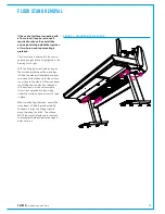
The PC monitor and keyboard tray are
fitted at the right hand side of the control
surface as standard. As an option,
consoles can be ordered with keyboard
and monitor at the left side of the surface.
The keyboard tray slides out from
SYSTEM PC
underneath the fader bed. If required, 2
PC monitors and / or keyboard trays can
be fitted, one at each end of the control
surface. The second set would typically
be used as a convenient location for
the operator to display / control other,
non-Calrec PC's. Consoles can also be
supplied without the monitor mount and
/ or keyboard tray, this is usually done
when space is restrictive. In such a case,
the installer should provide a suitable
alternative to view and control the system
PC.
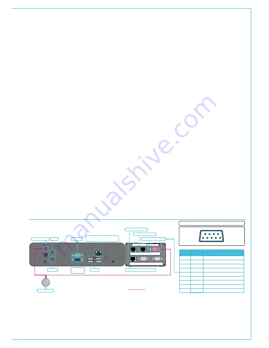
PCpowerandreset
The PC should start up automatically
when the control surface is powered.
The Windows shutdown procedure should
be followed whenever possible before
removing power to the control surface.
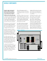
A reset switch for the PC is located at the
back of the keyboard tray.
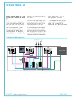
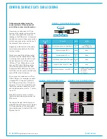
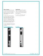
The power supply for the PC is located
in the adjacent unit which also contains
the headphone drivers. The PC power
supply inputs POE DC voltage via RJ45s
and outputs 12V DC on a 9 pin D-type
connector. Two input connections
provide redundancy against power loss
and should be fed from two different
POE switches, using their SPR feeds to
maintain power to the PC during surface
reset. The 9 pin connector also contains
a reset line for the PC which wires out to
a switch in the back of the keyboard tray.
The power input to the PC itself is via a
DC jack socket.
Systemnetworkdataconnection
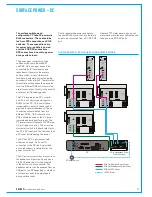
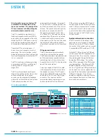
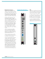
The PC connects to the system in the
same way as a control panel. The RJ45
Ethernet port on the PC itself is its data
connection to the system and can connect
to any available POE switch port P1–P6.
Note that P1–P6 ports are full POE and
contain power. The PC's supplied do not
take power from this connection, however
they are designed to be protected from
damage by POE voltage. Connecting
other PC's or equipment to a POE switch
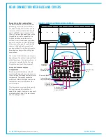
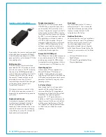
may damage them. The Ethernet-USB
adaptors supplied with the console (as
shown in Figure 2) are POE protected and
can be used to connect a replacement or
backup PC via the backup / replacements
USB port if required. One of these
adaptors is supplied loose along with the
miscellaneous items such as the backup
discs and hex screwdrivers.
Serial number
PC5787
POE SW 1
SPR1/2
POE SW 2
SPR1/2
PC POWER (+12V)
+ PC RESET
POE SW
SPARE PWR
BALANCED
ANALOG INPUTS
HEADPHONE
OUTPUTS
PC power input 1
POE PC power input 1
POE PC power input 2
12V power output to PC
POE Headphone driver power
PC 12V DC input
PC reset button
System PC
PC power & reset cable
Keyboard
Mouse
4 x USB
Serial port
Ethernet port - data connection
to system via POE panel port
VGA monitor
output
PC POWER AND RESET
1
2
6
7
3
4
8
9
5
9
8
7
6
9 Pin Male D-Type - Wiring side of connecting cable
1 2 3 4 5
Pin
Wired to
Signal
Reset
+12V
+12V
+12V
+12V
0V
0V
0V
0V
DC jack center pin
DC jack outer
Reset switch normally open
Reset switch Common
No connection
No connection
No connection
No connection
No connection
Содержание Artemis
Страница 5: ...calrec com Putting Sound in the Picture ARTEMIS INFORMATION...
Страница 9: ...calrec com Putting Sound in the Picture ARTEMIS CONTROL SURFACE...
Страница 26: ...26 ARTEMIS Digital Broadcast Production Console...
Страница 27: ...calrec com Putting Sound in the Picture ARTEMIS PROCESSING CORE BEAM SHINE...
Страница 33: ...calrec com Putting Sound in the Picture ARTEMIS PROCESSING CORE LIGHT...
Страница 40: ...40 ARTEMIS Digital Broadcast Production Console...
Страница 41: ...calrec com Putting Sound in the Picture ARTEMIS CONNECTION INFORMATION...
Страница 66: ...66 ARTEMIS Digital Broadcast Production Console...
Страница 67: ...calrec com Putting Sound in the Picture ARTEMIS EXTERNAL CONTROL...
Страница 80: ...80 ARTEMIS Digital Broadcast Production Console...
Страница 81: ...calrec com Putting Sound in the Picture ARTEMIS SETUP CONFIGURATION...
Страница 100: ...100 ARTEMIS Digital Broadcast Production Console...
Страница 101: ...calrec com Putting Sound in the Picture ARTEMIS PANEL OPTIONS...
Страница 110: ...110 ARTEMIS Digital Broadcast Production Console...
Страница 111: ...calrec com Putting Sound in the Picture ARTEMIS OBSOLETE PANELS...
Страница 114: ...114 ARTEMIS Digital Broadcast Production Console...
Страница 115: ...calrec com Putting Sound in the Picture ARTEMIS SPECIFICATIONS...

