16 ARTEMIS
Digital Broadcast Production Console
Control Surface
SURFACE COMPONENTS
There are a range of components
within the surface. This section
explains how these components
are connected, receive power and
communicate with each another.
POE(PowerOverEthernet)switch
Control panels in the surface have a single
connection that carries all data and power
via an RJ45 connector from a POE switch.
The number of POE switches fitted in
a control surface is determined by the
number of panels fitted. Each POE switch
can connect to up to six control panels.
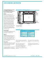
POE switches are mounted to the inside
of the rear cover and are accessible by
removing control and up-stand meter
panels, or by removing the rear covers as
shown in the Surface Dimensions and
Assembly section of this document.
Each POE switch has two AC mains
inputs and two PSU's to provide internal
and external power redundancy. 'Power
Good' LED's 1 & 2 indicate each power
supply is receiving mains and active.
A PSU failure or loss of a mains input will
generate a System Status error message.
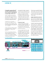
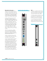
Each POE switch has 16 RJ45
connections, split into two groups - A & B.
The A group of connectors are full POE
- carrying both data and power. Status
LED's are provided for these ports which
should display a steady, regular flashing
pattern once the system is booted and
comms have been established.
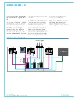
Connections P1 to P6 are used to
connect to control panels. Control panels
must be connected to the correct POE
unit and port, as defined by the Surface
Layout page in the main application. The
Surface Layout page, and other utility
software refers to these ports simply as
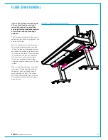
POE ports 1 - 6. See Figure 1.
When a surface reset command is
received by a POE switch it momentarily
cuts the power on ports P1 - P6. Control
surface panels are 'reset' by cycling power
to them.
Each POE switch requires a connection to
both the primary and secondary Surface
Switches. POE connector S1 connects to
the primary Surface Switch and connector
S2 connects to the secondary Surface
Switch. Although S1 & S2 are full POE,
power and data, Surface Switches do not
use the power from this feed.
Ports SPR1 & SPR2 are uninterrupted
during reset and are used to provide
power to the Surface Switches, PC and
any other items that may need to remain
powered during reset, such as ancillary
audio feeds. The SPR connections also
contain the reset lines from the up-stand
reset panel for the surface, control and
DSP which the active Surface Switch acts
upon accordingly. All other hardware,
such as the PC will ignore the reset lines
in the SPR feed.
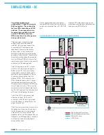
The B group of connectors do not pass
data. Ports AP1 - AP4 are ancillary
power, used to power 'non-intelligent'
units with no control processor or
data connection, such as moving coil
meters. AP connections drop power
during surface reset. Artemis up-stand
TFT panels do not have a direct data
connection from a POE. They have a
connection to a fader panel which carries
out the processing and passes on the
data to the display. Due to the size of
Artemis up-stand TFT's, the fader panel
cannot power them and therefore they
require an additional connection, from a
POE AP port for power only. See Figure 2.
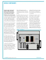
FIGURE 1 - POE SWITCH
P1
P2
P3
P4
P5
P6
S1
S2
USB
YZ5706 - POE SWITCH
P
S
AP
SPR
RST
AP1
AP2
AP3
AP4
SPR1
SPR2
RST
RST
A
B
2
1
POWER
GOOD
A
B
AC IN 1
AC IN 2
P1
P2
P3
P4
P5
P6
S1
S2
Panel
Surface switch
Ancillary Power
Surface switch
Power & Reset
Reset
-
-
-
-
-
Serial number
Содержание Artemis
Страница 5: ...calrec com Putting Sound in the Picture ARTEMIS INFORMATION...
Страница 9: ...calrec com Putting Sound in the Picture ARTEMIS CONTROL SURFACE...
Страница 26: ...26 ARTEMIS Digital Broadcast Production Console...
Страница 27: ...calrec com Putting Sound in the Picture ARTEMIS PROCESSING CORE BEAM SHINE...
Страница 33: ...calrec com Putting Sound in the Picture ARTEMIS PROCESSING CORE LIGHT...
Страница 40: ...40 ARTEMIS Digital Broadcast Production Console...
Страница 41: ...calrec com Putting Sound in the Picture ARTEMIS CONNECTION INFORMATION...
Страница 66: ...66 ARTEMIS Digital Broadcast Production Console...
Страница 67: ...calrec com Putting Sound in the Picture ARTEMIS EXTERNAL CONTROL...
Страница 80: ...80 ARTEMIS Digital Broadcast Production Console...
Страница 81: ...calrec com Putting Sound in the Picture ARTEMIS SETUP CONFIGURATION...
Страница 100: ...100 ARTEMIS Digital Broadcast Production Console...
Страница 101: ...calrec com Putting Sound in the Picture ARTEMIS PANEL OPTIONS...
Страница 110: ...110 ARTEMIS Digital Broadcast Production Console...
Страница 111: ...calrec com Putting Sound in the Picture ARTEMIS OBSOLETE PANELS...
Страница 114: ...114 ARTEMIS Digital Broadcast Production Console...
Страница 115: ...calrec com Putting Sound in the Picture ARTEMIS SPECIFICATIONS...

