CALREC
Putting Sound in the Picture
119
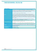
Power
All fixed format Hydra2 I/O units have two IEC AC power inlets and are fitted with dual power
supplies. Units will be fully functional on one PSU, however both should be fed where possible
from separate sources to provide redundancy against both PSU failure and external power loss.
The operating AC supply voltage is 100V–240V +/-10%.
The peak inrush current is limited (cold start). Figures are available for all units. This reduces the
chance of a nuisance trip or fuse blow from power up. The RMS quiescent current figures are
available for all types of I/O box.
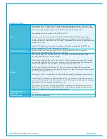
Power Factor
All fixed format Hydra2 I/O units require less than 75W of input power. The internal power
supplies fitted have passive filtering (as opposed to active power factor correction) to reduce the
harmonics to within the limits of the standard EN61000-3-2. At the time of writing the standard
does not apply to equipment <75W. If the lower limit is ever reduced the units will be compliant
and as such are future proof.
Heat Output & Efficiency
The Heat output from fixed format Hydra2 I/O units depends on the supply voltage and loading.
Typically it is 0.55 times the RMS VA (Volts x Amperes) at 230V and 0.7 times the RMS VA at
115V. Heat output figures are available for all types of I/O box.
The low power PSU efficiency is again dependant on supply voltage and loading, generally >70%.
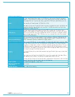
Cooling
All fixed format Hydra2 I/O units of 2U or greater are cooled under control with fan assistance.
Operation is not dependant on the fan; it is there to extend the operating life of the unit. There is
an 80mm low power, low speed and low noise fan mounted to the right hand side panel of each
unit venting air. Fan speed is monitored and System Status warnings generated if fans slow or fail.
Air is drawn in through the left hand side panel.
1U Hydra2 I/O boxes do not require fan assistance having sufficient surface area to radiate heat
adequately.
The side panels of all fixed format Hydra2 I/O units should be unobstructed with at least 50mm
(2') clearance to allow airflow. No clearance is required above or below the unit.
I/O units may be mounted in an open bay providing the ambient air temperature is within limits (see
below). The units may also be housed in any air conditioned bay.
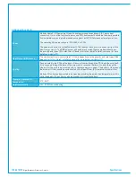
Acoustic Noise
<27 dB SPL (A-weighted, 1m from front).
Operating Ambient Air
Temperature
0°C - 35°C
Relative Humidity
5% – 80% Non-condensing
HYDRA2 FIXED FORMAT I/O
Содержание Artemis
Страница 5: ...calrec com Putting Sound in the Picture ARTEMIS INFORMATION...
Страница 9: ...calrec com Putting Sound in the Picture ARTEMIS CONTROL SURFACE...
Страница 26: ...26 ARTEMIS Digital Broadcast Production Console...
Страница 27: ...calrec com Putting Sound in the Picture ARTEMIS PROCESSING CORE BEAM SHINE...
Страница 33: ...calrec com Putting Sound in the Picture ARTEMIS PROCESSING CORE LIGHT...
Страница 40: ...40 ARTEMIS Digital Broadcast Production Console...
Страница 41: ...calrec com Putting Sound in the Picture ARTEMIS CONNECTION INFORMATION...
Страница 66: ...66 ARTEMIS Digital Broadcast Production Console...
Страница 67: ...calrec com Putting Sound in the Picture ARTEMIS EXTERNAL CONTROL...
Страница 80: ...80 ARTEMIS Digital Broadcast Production Console...
Страница 81: ...calrec com Putting Sound in the Picture ARTEMIS SETUP CONFIGURATION...
Страница 100: ...100 ARTEMIS Digital Broadcast Production Console...
Страница 101: ...calrec com Putting Sound in the Picture ARTEMIS PANEL OPTIONS...
Страница 110: ...110 ARTEMIS Digital Broadcast Production Console...
Страница 111: ...calrec com Putting Sound in the Picture ARTEMIS OBSOLETE PANELS...
Страница 114: ...114 ARTEMIS Digital Broadcast Production Console...
Страница 115: ...calrec com Putting Sound in the Picture ARTEMIS SPECIFICATIONS...

