Personal Ambulatory Oxygen System
Provider Technical Manual
88
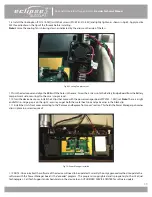
1.8 Install the Cooling Fan (PN: 1074-SEQ) with the 2 screws (PN: 6961-210-SEQ) and lightly tighten as shown in Fig 69. Apply Loctite
425 thread locker on the tips of the threads before installing.
Note:
Ensure the cooling fan is blowing down as indicated by the arrow on the side of the fan.
Fig 69: Cooling Fan placement
1.9 Turn the device over and align the BBB with the holes in the case. Screw the 4 screws into the Battery Bridge Board from the Battery
compartment side, securing it to the case (snug screws).
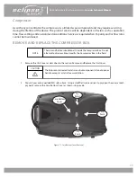
1.10 Turn the device back over. Install the 2 clips that come with the power manager board (SP5932-1-SEQ) set.
Note:
There is a right
and left clip - Large gap is on the right - ensure you get both the metal heat sink and pcb corner in the black clip.
1.11 Install the Unit’s front cover according to the “Remove and Replace front cover” section. This holds the Power Manager pcb corner
clips in place (no screw required).
Fig 70: Power Manager installed
1.12 NOTE: Once installed, the software of the device will need to be updated. Currently the only approved method to update the
software with this Power Manager board is the “eLoader” program . This program is copyrighted and is proprietary to Chart-SeQual
Technologies - Call Tech Support and schedule return the device to an AUTHORIZED SERVICE CENTER for software update.


