background image

Personal Ambulatory Oxygen System 

Provider Technical Manual

56

Troubleshooting, Service, and 
Repair Procedures

CAUTION


The Eclipse contains electrostatic sensitive components. Do not 

open or handle except at a static free workstation. Do not remove 

cover without ESD protection.

NOTE:

To adaquately troubleshoot and repair the product in the field, EDAT is recommended.

Eclipse Data Acquisition Tool (EDAT) PN 5535-SEQ

Содержание 1000B

Страница 1: ...PROVIDER TECHNICAL MANUAL Eclipse3 with autoSAT Personal Ambulatory Oxygen System PAOS Model 1000B...

Страница 2: ...e 21 Charging Algorithm 24 TABLE OF CONTENTS Training The Patient 25 Introduction 25 Pre Delivery Check List 25 Indications for Use 26 Contraindications 26 Basic Concept Training 26 Safety Guidelines...

Страница 3: ...55 Storing the Eclipse 55 Discarding 55 Troubleshooting Service and Repair Procedures 56 System Troubleshooting and Alarms 57 Alarm Conditions and Alarm Codes 60 Malfunction Codes 61 System Schematics...

Страница 4: ...inciples of operation Providers are given proper guidance in the use of the Eclipse 3 and its accessories that can be conveyed to patients Providers are made aware of the care diagnostics maintenance...

Страница 5: ...gen Outlet Port FAA Approval Icon BACK Power Cartridge Latch Exhaust Vent Power Cartridge Battery FAA Approval Icon Cart Attachment Location Air Inlet Filter EDAT Service Port Not for Patient Use Rati...

Страница 6: ...e Humidity 50 F to 104 F 10 to 40 C 10 to 95 Non condensing 82 4 F 28 C Maximum Dew point Storage Environment Temperature Humidity 4 F to 140 F 20 to 60 C Up to 95 Non condensing Altitude 0 13 123 fee...

Страница 7: ...ring Continuous Flow and waits 15 seconds for a breath The Eclipse 3 will stay in this modalityuntilabreathisdetected SeePowerCartridgeConservationFeature page26 Power Accessory Specifications AC Powe...

Страница 8: ...File MH29443 IEC 60601 1 1988 A1 1991 A2 1995 UN Transportation Tests T1 T8 Electromagnetic Compatibility EN 61000 6 3 2001 EN55022 1998 A1 2001 A2 2003 EN61000 6 1 2001 EN61000 4 2 1995 A1 1998 EN610...

Страница 9: ...anual Portable and mobile RF communications equipment can affect Medical Electrical Equipment TheuseofAccessories transducers andcablesotherthanthosespecified withtheexceptionoftransducersandcablessol...

Страница 10: ...1 kV line s to line s 2 kV line s to earth 1 kV line s to line s 2 kV line s to earth Mains power quality should be that of a typi cal commercial or hospital environment Voltage dips short interruptio...

Страница 11: ...RF transmitters as determined by an electromagnetic site sur vey a should be less than the compliance level in each frequency range b Interference may occur in the vicinity of equipment marked with th...

Страница 12: ...power of transmit ter W Separation distance according to frequency of transmitter m 150 kHz to 80 MHz 80 MHz to 800 MHz 800 MHz to 2 5 GHz 0 01 0 12 0 12 0 23 0 1 0 38 0 38 0 73 1 1 2 1 2 2 3 10 3 8 3...

Страница 13: ...The system monitors and controls both the power source and the Power Cartridge charger Figure 1 ECLIPSE System Block Diagram ATF CONCENTRATOR MODULE TheEclipseusesapassivesystemtoseparateoxygenfromair...

Страница 14: ...within the compressor enclosure serves to efficientlydrawcoolingairinoverthecompressorcylinderswhilesimultaneouslypushingexhaustgasoutoftheconcentrator POWER DISTRIBUTION ThePowerManagertakesexternalp...

Страница 15: ...d flow rate and flow mode ON OFF Button Green Indicator This button powers the device ON or OFF The Green Indicator is illuminated when the device is ON Increase or Decrease Setting Buttons Use these...

Страница 16: ...and orthePulseDosesettings mL EachtimeyoupowerthedeviceON thepreviousmodeand orsetting has been saved and will be used at start up Do not get wet PowerCartridge battery StatusGauge Thisindicatordispl...

Страница 17: ...es Regardlessofsetting thepulseprofileisasimplesquare wavepulsebasedona16mLvolume Referto PulseProfiles tablebelow Pulsedurationsarenolessthan100milli secondsatthebeginningoftheinspiration Therearethr...

Страница 18: ...ory effort The LCD will show PS x PS 1 is the most sensitive setting PS 3 is the least sensitive setting Factory defaut is PS 2 HOURS OF OPERATION TheEclipsehourmeterprovidesvaluableinformationonhours...

Страница 19: ...port needs EDAT software is capable of sensing and displaying historical event logs and values of components and sensors within the Eclipse system This can be used to determine system faults or user e...

Страница 20: ...srequiretheuseofhospitalgradeACpowercordwiththeEclipse Figure 5 Eclipse 3 AC Power Supply TheEclipse3ACPowerSupplydoesnotcontainafan Wheninuse theACPowerSupplyshouldbelocatedinawell ventilated area Lo...

Страница 21: ...power on DC DO NOT use the DC supply to power the Eclipse once the vehicle s engine is turned off as this may drain the car s battery POWER CARTRIDGE BATTERY ThePowerCartridgeallowsoperationawayfromA...

Страница 22: ...mmercialairlineflightforinternationaltravel removethePowerCartridgeand properly package When shipping the Eclipse for any reason remove the Power Cartridge from the Eclipse IfthePowerCartridgegetstoow...

Страница 23: ...urefallswithintheselimits theEclipsewillresumenormaloperation Operationnearthesetemperaturelimitswill not damage the Power Cartridge but are in place to ensure that the service life of the Power Cartr...

Страница 24: ...ventuallyfall Whenthechargingcurrentfor eachPowerCartridgehasfallenbelow5 oftheratedcapacity chargingiscompleteandthePowerCartridgechargerisshut off The software will only charge when the Power Cartri...

Страница 25: ...IST Before delivering the device check and log the status of the following Parts Inventory Verify that each Eclipse is provided to the patient with the following items a Users Manual a Quick Start Gui...

Страница 26: ...fetyWarnings Cautionswitheachpatient Inaddition provider shouldcarryoutariskassessmentpriortoinstallationoftheEclipsetoassureproperconnectionandcompatibilitywithother equipment the patient may be usin...

Страница 27: ...dindicatorcanbefound in the Eclipse Users Manual CAUTION Some patients are highly mobile and may use the device under varying circumstances Make sure your patient or patient caregiver completely under...

Страница 28: ...ate the procedure for your patient Set the prescribed flow using the increase or decrease buttons Verify that the patient is able to adequately trigger the oxygen delivery while speaking sitting quiet...

Страница 29: ...selectingsetting1 2or3 1 most sensitive 3 leastsensitive ThedefaultsettingforunitscomingfromSeQualis 2 ToadjustthePulseSensitivity performthe following steps 1 Have the patient sit quietly with the na...

Страница 30: ...t the power cord into the AC Power Supply 3 Plug the power cord into a grounded outlet 4 The power supply LED displays green to indicate that the AC Power Supply is drawing power The External Power Pr...

Страница 31: ...mode will also not operate above 96 mL Ensure adequate clearance around the DC Power Supply and the Eclipse Ensure the DC Power Supply and Eclipse are secured in the vehicle so that is does not become...

Страница 32: ...by vehicle If so show your patient how to safely use the Eclipse while driving Refer to the previous section on Connecting the DC Power Supply for proper setup of the Eclipse system in a vehicle Figur...

Страница 33: ...xtreme temperatures Extreme heat or cold may impair operation and damage the device and degrade the Power Cartridge WARNING NOTE Actual performance of the Eclipse may vary depending upon usage conditi...

Страница 34: ...the Power Cartridge DO NOT use DC or ACPowerAdaptersonanaircraft ThepatientmustensurethattheyhaveanadequatenumberofsparePowerCartridgesto last for the duration of their trip Visitourwebsite www sequal...

Страница 35: ...t information for the tubing and cannula CLEAN THE CABINET AND CONTROL PANEL AND POWER SUPPLIES To clean the cabinet Control Panel or power supply do the following 1 Turn OFF the Eclipse and discon ne...

Страница 36: ...he patient will need an AC Power Supply to recharge the Power Cartridge and should be able to run the Eclipse from AC power for at least 5 hours The patient should follow these steps 1 Install the Pow...

Страница 37: ...se Panel Buttons and Indicators Alerts and Alarms Power Cartridge Power Level Selecting Flow Mode and Setting Selecting Continuous Flow Mode Selecting Pulse Dose Mode with autoSAT Technology Adjusting...

Страница 38: ...Pulse Dose Mode and alarm functions Replace compressor intake filter Perform electrical safety test Required only for PN 5701 Hospital Grade Power Cord Replace HEPA filter CHECKING AND REPLACING THE...

Страница 39: ...utting pliers Small cable ties ESD Mat or approved ESD system Figure 11 Maintenance Tools REMOVING THE UNIT COVER 1 Disconnect power supplies and remove Power Cartridge before removing the unit cover...

Страница 40: ...er pop the bottom end off first and rotate it towards the handle Be careful not to tear the Control Panel ribbon cable that is attached to the front cover Figure 13 Opening the Front Cover CAUTION The...

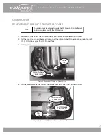
Страница 41: ...This may damage the pins of the header Figure 14 Removing the Membrane Panel Overlay Ribbon Cable 7 Disconnect the silicone tube from the oxygen outlet tube at the top of the cover First cut the cabl...

Страница 42: ...cting the Oxygen Outlet Tube 8 Lay the front panel away from Eclipse Inspect PEM Nut anchors in the front cover assembly Perform necessary maintenance Figure 16 Front Cover Removal Once the cover has...

Страница 43: ...mpartment located at the bottom right corner of the unit Figure 17 Removing the 9 volt Battery 3 Disconnect the 9 volt battery harness 4 Remove and replace the 9 volt battery Figure 18 Disconnecting t...

Страница 44: ...to the HEPA filter Figure 19 Removing the HEPA Filter 2 Disconnect both tubes from the filter hose barbs Figure 20 Disconnecting the HEPA Filter 3 Remove and replace the filter NOTE Always cut the hea...

Страница 45: ...gure 21 Installing the HEPA Filter 5 Re install cable ties on silicone tubes NOTE Route tubing as shown in Figure 22 Install cable ties loosely as shown CAUTION Once the silicone tubes are disconnecte...

Страница 46: ...46 2 Unscrew the wing nut that hold the HEPA filter Figure 23 Wing Nut 3 Unscrew the Clear HEPA filter and discard Filter small O Ring Figure 24 Unscrewing the HEPA Filter 4 Install the new small O ri...

Страница 47: ...R INTAKE FILTER Replace the compressor intake filter annually or more often as needed The compressor intake filter may become clogged depending upon the amount of contaminants in the air smoke dust di...

Страница 48: ...es attached to each end of the filter body 3 Install a new filter by pushing each tube completely over the barb on the filter body Verify flow direction is correct 4 Reconnect silicone tubes to the fi...

Страница 49: ...or a minimum of 20 minutes prior to re installing the cover to check for a smooth and quiet calibration to be replaced by operation Tore installthecover followthestepsusingthereverseorder Ensurethatth...

Страница 50: ...oncentrator on and set the target flow on the Eclipse to 3 LPM continuous flow Allow the Eclipse to stabilize can take up to 10 minutes Verify the O2 concentration and O2 flow rate are within specific...

Страница 51: ...he Control Panel by pressing each of the Increase Decrease Pulse Dose Mode and No Smoking buttons and observe that the Eclipse buttons function normally 5 Press the Delivery Mode button and set the Ec...

Страница 52: ...to 00 000 Alarm Code ALRM Displays most recent alarm code Additional alarm codes will also be displayed if present by continuing to press the key Pulse Sensitivity PS Hours of Operation HRS 9 volt Ba...

Страница 53: ...er Supply from the electrical safety analyzer 5 If the AC Power Supply measures leakage current greater than the criteria in step 3 please return it to SeQual for service 6 EDAT may be utilized to rec...

Страница 54: ...ftheEclipseisopened theflowrate purity and alarm status should be verified per the Test Procedures in this manual EDAT may be utilized to record Eclipse device status and dates of service Eclipse Seri...

Страница 55: ...artridge when storing the device The Eclipse must be turned on and run for 2 hours each month to ensure proper operation performance Tip Running the power cartridge down completely and recharging it w...

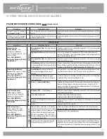
Страница 56: ...ures CAUTION The Eclipse contains electrostatic sensitive components Do not open or handle except at a static free workstation Do not remove cover without ESD protection NOTE To adaquately troubleshoo...

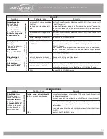
Страница 57: ...lug it in to AC power and allow to recharge fully Replace battery if it does not come back within specification Any Power Source Yellow Light is Blink ing and Unit is beeping Low or No Oxygen Flow Pre...

Страница 58: ...e to come up to Green Light operation Other Contact Chart TS for RMA service Eclipse Red Light and Alarms Battery has become Too Hot FAIL Condition Displayed FAIL XX Battery is too Hot and will not op...

Страница 59: ...r DC Unit will beep for loss of external power AC power is loose or not connected Plug device directly into known good AC outlet extension cord and com puter strips are not recommended DC power is loo...

Страница 60: ...O2 85 OFF Flashing OFF OFF PerformAnnualFilterPMMaintenance Ifconditionpersists service is required O2Concentration 70 004 O2 70 OFF OFF Flashing 3 Beeps PerformAnnualFilterPMMaintenance Ifconditionp...

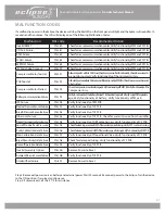
Страница 61: ...wEclipsetocoolfor30Minutes VerifyfunctionalityofPMfan Checktoensureventsarenot obstructed Compressor Motor Stalled FAIL 94 CheckCompressorwiresfordamage VerifyfunctionalityofPMPCB Verifyfunctionalityo...

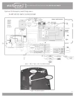
Страница 62: ...onal Ambulatory Oxygen System Provider Technical Manual 62 System Schematics and Diagrams SIMPLIFIED BLOCK DIAGRAM Figure 31 Eclipse 3 Oxygen System Simplified Block Diagram Figure 32 Top Case Compone...

Страница 63: ...gen System Provider Technical Manual 63 Figure 33 Bottom Case Components ATF Module Product Tank Compressor Box Compressor Intake Filter Control Board Battery Bridge PC Board HEPA Filter Power Manager...

Страница 64: ...er Technical Manual 64 Figure 34 Bottom Case Components Eclipse 3 Manufactured December 2011 and above ATF Module Product Tank Compressor Box Compressor Intake Filter Control Board Battery Bridge PC B...

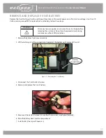
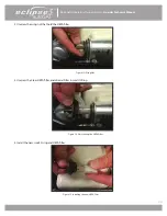
Страница 65: ...as described in the section Remove and Replace the Unit Cover 2 Cut the green tie as shown below and disconnect the silicone tube that goes into the product port of the ATF this tube comes from the P...

Страница 66: ...screws and washers M4 Flat washer P N 6985 04 as shown below Figure 37 Remove ATF Module from Eclipse Case 7 Lift the ATF Take off the 3 grommets Disconnect the wire harness from the gearbox of the A...

Страница 67: ...before installing Tighten screws but DO NOT squash the grommets 2 in lbs maximum NOTE Inspect all tubing before securing with a cable tie CAUTION Remove caps on ATF ports ONLY before connecting the tu...

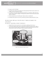
Страница 68: ...lacement 16 Installation of the Unit Cover on the unit is described in the Remove and Replace of the Unit Cover REMOVE AND REPLACE THE PRODUCT TANK ASSEMBLY PN 6138 SEQ ECLIPSE 1 ECLIPSE 2 EARLY ECLIP...

Страница 69: ...ties Inspect the tubing to ensure the tubing is not kinked 7 Install the silicone tube that comes from the ATF product port to the bottom Product Tank as shown in Figure 40 on previous page Secure wi...

Страница 70: ...Use the picture below as an aid to ensure proper routing of oxygen tubing in the Eclipse Figure 42 Oxygen Tubing Routing Tube from ATF Module to Product Tank 4 5 long Tube from Product Tank to Flow C...

Страница 71: ...failure of one of its components then follow steps for Situation 3 Situation 3 If you are just replacing the HEPA filter then follow the steps in the PM section for Remove and Replace HEPA Filter Sit...

Страница 72: ...screws Set aside for re installation Figure 44 Figure 44 Remove Screws 5 Lift out the old product tank PN 6138 SEQ Set aside for RMA return or scrap Install new Product Tank PN SP4378 SEQ or 4378 SEQ...

Страница 73: ...t tank and locate the screw hole on the back case cover for the old product tank securing arm that was to the right top side of compressor See Figure 47 Figure 47 Install securing arms 4 Locate the Pr...

Страница 74: ...eplace the Front Cover Assy on page 40 2 Remove the Front Cover Assy completely outlet tubing and front membrane ribbon cable Set aside 3 LocatethemetalProductTankandcutthecabletiesfromtheATFtotheProd...

Страница 75: ...ws that hold the securing straps and the product tank in place remove the screws Set aside for re installation Figure 50 Fig 50 Remove screws 8 Lift out the old product tank PN 4378 SEQ Set aside for...

Страница 76: ...Power Manager PC Board Communications ProportionalValve wire harness and Buzzer wire harnesses as shown in Figure 51 Cable Tie Screw Tube from Product Tank Tube from the Proportional Valve Buzzer Conn...

Страница 77: ...e Placethe2screwsinthesheetmetalbracketasshowninFigure52 Inspectthetubing to ensure the tubing is not kinked 8 Lower the Control Board Assembly into the Unit Case only to where the aligning pins go th...

Страница 78: ...stall a new buzzer apply a ring of cyanoacrylate adhesive Super Glue around the inlet hole as shown in Figure 53 Figure 53 Bonding the Buzzer to the case 5 Placebuzzerasshowninfigure54 Ensurethatthebu...

Страница 79: ...e figure below as an aid to ensure proper connection of wire harnesses to the Power Manager printed circuit board Figure 55 Control Board Connector Diagram Buzzer Connector Air Inlet Temperature Data...

Страница 80: ...artridge and unscrew the 4 screws M3x12 Pan Head SEM Screw P N 6974 312 SEQ shown in Figure 56 Figure 56 Battery Bridge Board Removal 2 Remove the Unit Cover as described in the section Remove and Rep...

Страница 81: ...anager PC Board Removal 4 Unscrew the 2 screws M2x10 Pan Head Machine Screw P N 6961 210 SEQ holding the fan shown in Figure 49 Remove fan 5 Remove the Exhaust Tube shown in Figure 58 Figure 58 Exhaus...

Страница 82: ...sition the Power Manager PCB into the slots on the Unit Case 8 Install the fan with the 2 screws and lightly tighten as shown in Figure 57 Apply Loctite 425Thread Locker on the tips of the screws befo...

Страница 83: ...e below as an aid to ensure proper connection of wire harnesses to the Power Manager printed circuit board Figure 60 Power Manager PC Board Connector Diagram Early Production E3 Compressor Blower ATF...

Страница 84: ...4 POWER MANAGER PCB IDENTIFICATION Use the picture below as an aid to ensure proper connection of wire harnesses to the Power Manager printed circuit board Figure 61 Previous Separate PM pcb and BBB p...

Страница 85: ...63 Screws 1 2 Remove the Unit cover as described in section Remove and Replace the Unit Cover 1 3 Disconnect the 5 wire harnesses as shown in Figure 54 Remove the Battery Bridge pcb BBB pcb as shown...

Страница 86: ...ust Tube 1 6 Pull the Power Manager pcb 1 out of the case Gently push the compressor box away from the Power Manager pcb about 1 8 Slide the board and the cabling out from under the edge of the compre...

Страница 87: ...g58 GentlypushtheCompressorBoxaway from the Power Manager pcb by 1 8 Connect the 2 wire harnesses Ext Power ATF harness and the Control Board Ribbon Cable Note Routethewiringundertheedgeofthecompresso...

Страница 88: ...ck over Install the 2 clips that come with the power manager board SP5932 1 SEQ set Note There is a right and left clip Large gap is on the right ensure you get both the metal heat sink and pcb corner...

Страница 89: ...r is a limited wear component and may require servicing during the lifetime of the device The point of service will be dependent on factors such as operation time flow settings and environmental condi...

Страница 90: ...Power Wire Harness Compressor Signal Wire Harness 3 Disconnect the 3 wire harnesses shown in Figure 72 Figure 72 Compressor Box electrical connections 4 Remove the Exhaust Tube as shown in Figure 73 F...

Страница 91: ...fitting vinyl caps or vinyl electrical tape Figure 74 Removal of Compressor Pressure and Vacuum Hoses from ATF Module CAUTION Once the braided hoses are disconnected from the ATF Module the ATF Module...

Страница 92: ...n previous page Secure joints with cable ties 11 Use a cable tie to secure the silicone tube to the braid tube to ensure that there is NO kinking on the bend as shown on Figure 74 on previous page Han...

Страница 93: ...Supply 5942 SEQ Foot bottom 6956 SEQ Handle 6963 SEQ Inlet Filter 7028 SEQ Membrane Panel Overlay Eclipse 3 SP4225 SEQ Nut Outlet 2777 SEQ Outlet Assembly Oxygen 3922 SEQ Power Manager PCBA Eclipse 3...

Страница 94: ...SEQ If your physician has prescribed an optional hu midifier youmayneedtousetheSeQualHumidifierAdapter Followtheinstructionsforuse AttachtheHumidifierAdapterto theoxygenoutletportoftheEclipseandthento...

Страница 95: ...a chart ind com www CAIREmedical com AUTHORIZED EUROPEAN UNION REPRESENTATIVE Medical Product Services GmbH Borngasse 20 35619 Braunfels Germany E mail techservice europe chart ind com www CAIREmedica...

Отзывы: