Personal Ambulatory Oxygen System
Provider Technical Manual
81
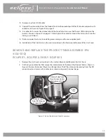
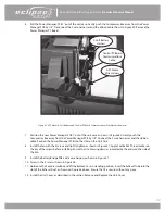
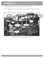
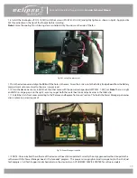
3. Disconnect the 5 wire harnesses as shown in Figure 49. Remove the Battery Bridge PCB as shown in Figure 57.
Figure 57: Power Manager PC Board Removal.
4. Unscrew the 2 screws (M2x10 Pan Head Machine Screw, P/N 6961-210-SEQ) holding the fan shown in Figure
49. Remove fan.
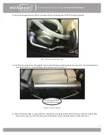
5. Remove the Exhaust Tube shown in Figure 58.
Figure 58: Exhaust Tube Removal.
Exhaust
Tube
Blower Wire
Harness
External Power
Wire Harness
Battery Bridge
Board
Compressor Power
Wire Harness
Cooling Fan
Wire Harness
Compressor Signal
Wire Harness
Screw


