background image


OPERATION


MANUAL


Manual Order Number: 1036315 

Copyright  © 2009 MKS Instruments, Inc. All rights reserved.


Revision Level: 00A 

MATCHWORK

®

 is a registered trademark of MKS Instruments, Inc. 


elite

TM


RF


Plasma


Generator


elite


300


/


600


/


750


WARNING:


POTENTIALLY


LETHAL


VOLTAGES


ARE


USED


BY


AND


PRODUCED


BY


THIS


UNIT.


A


thorough


understanding


of


this


manual


is


required


before


attempting


to


install


this


unit


into


a


system.


CFC's


DO


NOT


USE


ANY


CFC


(CHLOROFLUOROCARBON)


SOLVENT


IN


THE


MAINTENANCE


OF


THIS


PRODUCT.


In


recognition


of


our


responsibility


to


protect


the


environment,


this


product


has


been


manufactured


without


the


use


of


CFCs.


The


no

clean


flux


now


used


in


all


soldering


operations


may


leave


a


small


inert


residue


that


will


not


affect


the


performance


of


the


product.


The


use


of


CFCs


for


cleaning


or


maintenance


may


result


in


partial


liquification


of


the


no

clean


flux


residue,


which


will


damage


the


unit


and


void


the


warranty.


ISO 9001

QUALITY

SYSTEM


This


product


is


manufactured


at


an


MKS


Instruments’


ISO

9001

Quality

System

compliant


facility.


Notice


The


material


contained


in


this


manual


is


subject


to


change


without


notice.


No


part


of


this


manual


may


be


reproduced


or


utilized


in


any


form


or


by


any


means,


electronic


or


mechanical,


including


photocopying


or


electronic


transmission


or


other


means


of


reproduction


or


distribution


without


prior


written


consent


of


MKS,


ENI


Products.


The


drawings,


specifications


and


other


technical


information


contained


in


this


manual


are


the


property


of


MKS,


ENI


Products


and


shall


not


be


copied,


reproduced


or


used


in


any


way,


in


whole


or


in


part,


as


the


basis


of


manufacture


or


sale


of


similar


items


without


the


prior


written


consent


of


MKS,


ENI


Products.


Содержание elite 300

Страница 1: ...nce of the product The use of CFCs for cleaning or maintenance may result in partial liquification of the no clean flux residue which will damage the unit and void the warranty ISO 9001 QUALITY SYSTEM...

Страница 2: ...OM ANY CAUSE WHATSOEVER INCLUDING NEGLIGENCE Buyer s sole and exclusive remedy under this warranty shall be repair or replacement as set forth above or if MKS ENI Products is unable to repair or repla...

Страница 3: ...ngen Stetten Stuttgart Germany Tel Fax 49 711 947700 49 711 9477025 JAPAN 1 21 15 Aoyagi Kunitachi Tokyo 186 0013 Japan Tel Fax 81 425 229 011 81 425 222 636 KOREA 1ST Floor DK Plaza I 375 1 Geumgok d...

Страница 4: ...This page intentionally left blank...

Страница 5: ...ngle 10 1 2 3 Service Warning 10 1 2 4 Non ionizing Electromagnetic Radiation Warning Triangle 11 1 2 5 Technical Support 11 1 2 6 Earth Ground 12 1 2 7 Protective Earth Ground 12 1 2 8 Frame or Chass...

Страница 6: ...ions and indicators 27 Status LEDs 29 2 9 Power Requirements 31 2 9 1 AC Mains Connection 31 2 11 Maintenance Cleaning 32 2 12 System Check 33 Chater 3 eliteTM Operation 34 3 1 Basic Operation through...

Страница 7: ...Contents eliteTM iii Chapter 4 Troubleshooting 44 4 1 Hardware Faults 44 Appendix A eliteTM Specifications 45 Appendix B Glossary of Terms 48...

Страница 8: ...Contents iv eliteTM This page intentionally left blank...

Страница 9: ...er output within 2 of set point over a Dynamic Power Range of 1 to 300 600 or 750 watts The RF output can be pulsed at up to 1kHz with duty cycles from 1 to 99 Precise power calibration is traceable t...

Страница 10: ...ructions are also given in Chapters 2 and 3 It is essential that you become thoroughly familiar with the contents of this manual prior to using your generator If used properly the information containe...

Страница 11: ...on Chapter 2 This chapter acquaints the user with the eliteTM Plasma Generator It covers major features and front and rear panel descriptions This chapter covers everything needed to install and set u...

Страница 12: ...ckets These brackets are shown for command parameters They are not part of the command and should not be entered Rounded Brackets These brackets contain hex equivalent numbers for printable or non pri...

Страница 13: ...ices The term WARNING is used to indicate a potential hazard that could result in injury or death if not avoided The term DANGER is used to indicate an imminent hazard of serious injury or death if no...

Страница 14: ...nsulated voltage within the enclosure of sufficient magnitude to constitute a risk of electric shock Only authorized service personnel with a schematic diagram and a thorough knowledge of the voltages...

Страница 15: ...e Symbol Definition Caution non ionizing electromagnetic radiation The non ionizing electromagnetic radiation warning triangle symbol reference IEC Publication 417 Symbol No 5140 and ISO Publication 3...

Страница 16: ...licitly required 1 2 7 Protective Earth Ground Symbol Definition Protective earth ground The protective earth ground symbol reference IEC Publication 417 Symbol No 5019 is used to identify equipment t...

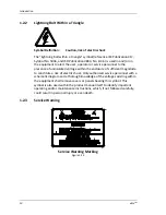
Страница 17: ...liteTM Serial Tag Label Figure 1 3 A ENI MODEL NUMBER The number that uniquely identifies the unit D ENI REV The revision letter identifying product configuration Revision A is the initial revision le...

Страница 18: ...of the generator 2 Attach the AC Mains line cord to a 100 264V single phase 15 A outlet See section 2 9 for more information on AC Power Requirements 3 If applicable connect the 9 pin male serial digi...

Страница 19: ...recautions when RF power is active 7 If the generator is equipped with an ON OFF switch move the switch to the ON position If the switch has no ON OFF switch simply plug in the IEC linecord to the rea...

Страница 20: ...eturn the unit should this become necessary 2 1 3 Packaging for Reshipment Whenever possible the original shipping carton and packing material should be used for reshipment If the original packing mat...

Страница 21: ...handle full rack 331012 Rack handle half rack 1039014 RF Connectors Cover RF Output Connector cover 1036305 001 Connectors AC Cord Interlock Jumper 1019388 001 Basic AC linecord IEC 60320 C 13 to NEMA...

Страница 22: ...n include an upstream current limiting disconnect device rated 50 60 Hz 250V minimum and no more than 20A The upstream disconnect device must be located within sight of the eliteTM unit must remain us...

Страница 23: ...n the rear panel to the chassis ground on the cabinet For details refer to the applicable Mounting and Outline Drawing as detailed in section 2 1 4 2 4 System Interconnect The eliteTM generator may be...

Страница 24: ...upra Shield or equivalent cable and metallized backshells providing 360 shield termination 2 5 1 Communication Configuration A standard 9 pin female Type D connector provides the electrical connection...

Страница 25: ...able must be used for the RF output connection 2 7 Safety Interlocks For user safety the eliteTM generator is equipped with an RF interlock system accessed through pins 10 and 23 of the 25 pin D sub c...

Страница 26: ...ion 22 eliteTM 2 8 Panels and Controls This section describes in detail all the front and rear panel controls and connections used on your generator elite LCD Front View Figure 2 8a elite Basic Front...

Страница 27: ...applicable the attached MKS Matchworks The six button keypad can be used to setup the generator and Matchworks operating parameters and control the RF output The LCD has two different menus that can b...

Страница 28: ...M ENTRY DESCRIPTION ON RF is ON RF STATUS OFF RF is OFF FP Forward Power Leveling Mode LP Load Power Leveling Mode LVL MODE EX External Leveling Mode DC Bias FWD 0 750 Forward Power Watts REV 0 200 Re...

Страница 29: ...eTM 25 Pulse Menu PL DUTY 10 FREQ 1000Hz STATUS DUTY FREQUENCY MENU ITEM ENTRY DESCRIPTION CW RF output is CW continuous wave STATUS PL RF output is pulsing DUTY 1 99 Pulsing duty cycle FREQUENCY 1 10...

Страница 30: ...ecrement value of the selected control parameter When cursor mode is disabled the DOWN key can be used to switch from the Main menu to the Pulse menu LEFT In cursor mode push to move to the next contr...

Страница 31: ...nterface allows control of the generator through various analog voltages 0 10Vdc See section 3 2 1 for more information RS 232 Interface Type DB9F This interface is used to connect the generator to a...

Страница 32: ...ork when the optional Profibus Interface Board is installed This allows the generator to control the Matchworks capacitor positions via the generator front panel control Profibus Connector Type DB9F T...

Страница 33: ...active In the case of multiple faults or warnings there will be a one second OFF period between codes Status PWR LED STAT LED AC ON Solid Green System Ready Solid Green Solid Green RF On Flashing Gree...

Страница 34: ...e from the previous page Chassis Ground AC Input RF Output CEX In CEX Out DC Bias Optional Matchwork Interface Profibus Address dipswitch Profibus Connector Status LEDs Analog Interface Connector Prof...

Страница 35: ...e supplied from two Hot conductors that meet the AC voltage range for the unit i e 220V single phase two phases of 208V 3ph 2 9 1 AC Mains Connection An IEC 60320 C 13 style AC appliance inlet is supp...

Страница 36: ...y cloth to remove any build up of dust and dirt When operated in dusty areas dust may build up in the front air intakes A hand held vacuum cleaner can used to remove any dust build up that occurs or i...

Страница 37: ...s Inspect the AC power connector and cable before use replace if damaged 2 The RS 232 serial cable if used is connected to the 9 pin D type serial connector on the rear panel 3 The Analog Interface Ca...

Страница 38: ...enerator is designed to be used with minimal input from the user In the most basic case all that is required from the user is an RF setpoint and the RF ON command In more advanced situations other com...

Страница 39: ...lly entered by the user In the examples that follow it will be shown to indicate command entry at the terminal and is only included for completeness 3 1 3 Startup Message If you are connected to the u...

Страница 40: ...mand NAK CR LF ASCII 0x0D 0x0A 0x3F This is used to indicate that the command sent was invalid or unavailable 3 1 5 Optional Argument Data Entry Integer Numbers are entered as just where the number is...

Страница 41: ...achieve P Power Setpoint XXXXXX Sets the power setpoint for the generator After the P command is issued the generator will respond with Enter New Setpoint AAAAAA BBBBBB The power setpoint must be ent...

Страница 42: ...ata can be easily used by a user built script or macro The data is returned in the following format 000000 000000 0000000000000000 0000000000001000 000056 000024 000032 000000 000005 00004E20 00004E20...

Страница 43: ...Operation EliteTM 39...

Страница 44: ...RF on enable pulse mode wait for some time and then turn RF Off User Entry Description E Enable RS 232 control P 000750 Set power set point to 750W N Turn RF on Q 000050 Set pulse high time to 50 us...

Страница 45: ...er level 0 V 0 W and 1 V 75 W Input impedance is 100 k balanced differential to ground 6 NOT USED 7 RF ON E DO Emitter side of isolated transistor switch See Note 1 Transistor ON RF ON Transistor OFF...

Страница 46: ...No fault 23 INTERLOCK This pin should connect to Pin 10 to complete the interlock chain 24 BLANKING Pulse blanking signal Ground referenced logic input LOW or OPEN RF Pulse on HIGH RF Pulse Off The no...

Страница 47: ...F setpoint a momentary overshoot of RF power may be occur if a CEX signal is applied after RF is already turned on 3 3 Pulsed Operation The eliteTM generator is capable of both CW and pulsed operation...

Страница 48: ...supplied Unit does not power up when plugged in and or power switch in ON position Internal fuse open Contact an authorized MKS ENI Products Service location for assistance INTERLOCK fault Interlock...

Страница 49: ...Appendix A EliteTM 45 Appendix A eliteTM Specifications This appendix lists the complete physical and electrical characteristics for the eliteTM Plasma Generator...

Страница 50: ...0 5ms when reflected power exceeds 200W Commanded Power Accuracy 2W 1W 100W 2 101 rated power Same Generator Repeatibility 1 Dynamic Power Range 1W to rated power RF Stability Spurious Output Uncondi...

Страница 51: ...Temperature 5C to 40C Size 17 W x 15 D x 3 5 H Weight 25lbs 11kg Rack Mounting Integral 19 inch rack ears RF Output Connection Type N Interfaces RS 232 Std Analog Opt Profibus Opt DB9F DB25F DB9F Int...

Страница 52: ...imminently hazardous situation that if not avoided will result in death or serious injury EMC Electromagnetic Compatibility Enclosure A part providing protection of equipment against certain external...

Страница 53: ...boratory Operator Person operating equipment for its intended purpose Pollution Any addition of foreign matter solid liquid or gaseous ionized gases that may produce a reduction of dielectric strength...

Страница 54: ...A component provided for the connection of a device equipment to external conductors It may contain one or several terminal contacts Tool An external device including keys and coins used to aid a per...

Страница 55: ...Appendix B EliteTM 51 This page intentionally left blank...

Отзывы: