


2-8
Unpacking and Installing Your SmartSTACK Ethernet ELS10-27
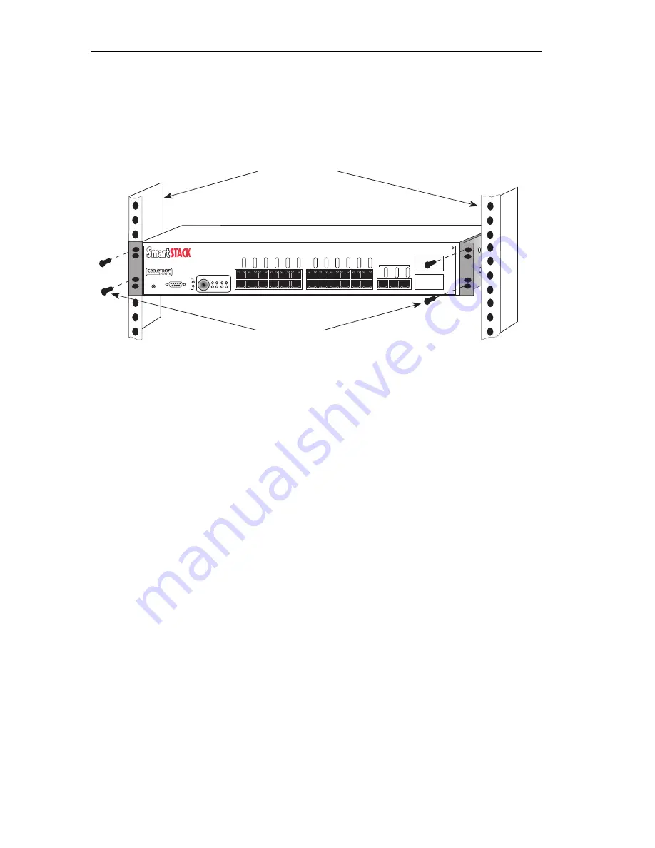
3. Secure the SmartSTACK Ethernet ELS10-27 with the rackmount
fasteners by inserting and securing a fastener through each of the
four slots in the rack-mount brackets, as shown in Figure 2-4.
Figure 2-4. Rack-mounting the SmartSTACK Ethernet ELS10-27
4. Once the SmartSTACK Ethernet ELS10-27 is installed, plug the AC
power cord into the AC power connector on the rear of the
SmartSTACK Ethernet ELS10-27 chassis. Plug the other end of the
power cord into a three-prong grounded outlet.
2.4 CHECKING THE POWER-UP DIAGNOSTICS
SEQUENCE
Before connecting any devices to the SmartSTACK Ethernet ELS10-27,
power on the unit and observe the power-up diagnostics sequence to
check for proper operation.
To observe the power-up diagnostics sequence completely, you may want
to repeat it. To restart the power-up sequence, press the reset button on
the front panel.
When you power up the SmartSTACK Ethernet ELS10-27, the following
occurs:
1. Power LED is ON.
2. CPU LED comes on.
3. Segment Status LEDs Sequence as Initialize Progresses.
Screws (4)
19-Inch Rack
2X 4X 6X 8X 10X 12X
14X 16X 18X 20X 22X 24X
26
27
RESET
ELS10-27TX
EPIM100
PWR
CPU
ETHERNET SWITCH
25X 26X 27X
10BASE-T/100BASE-TX
COM
LINK
ST
A
TUS
LINK
ST
A
TUS
LINK
ST
A
TUS
LINK
ST
A
TUS
LINK
ST
A
TUS
LINK
ST
A
TUS
LINK
ST
A
TUS
LINK
ST
A
TUS
LINK
ST
A
TUS
LINK
ST
A
TUS
LINK
ST
A
TUS
LINK
ST
A
TUS
LINK
ST
A
TUS
LINK
ST
A
TUS
LINK
ST
A
TUS
PORT STATUS MODE
STATUS
TX
ACT
FDX MON
RX COL
100 USR
Содержание SmartSTACK ETHERNET ELS10-27
Страница 2: ......
Страница 12: ...Notice x...
Страница 16: ...xiv Contents...
Страница 74: ...2 14 Unpacking and Installing Your SmartSTACK Ethernet ELS10 27...
Страница 94: ...3 20 Configuring Your SmartSTACK Ethernet ELS10 27...
Страница 108: ...4 14 Monitoring and Managing Your SmartSTACK Ethernet ELS10 27...
Страница 122: ...A 8 EPIM 100FX...
Страница 126: ...Index I 4...


