26
A 8
3
4
2
1
6
7
5
8
9
9
5.2
Wechsel des Druckkopfes und
des Druckkopfkabels
ACHTUNG!
Sachschäden durch elektrostatische
Aufladung! Erden Sie sich vor dem
Entfernen oder dem Einbau des Druck-
kopfes am Gehäuse. Dadurch wird der
Druckkopf vor einer statischen Entla-
dung Ihres Körpers geschützt.
Wechsel Druckkopf:
1. Drucker ausschalten, Deckel öffnen.
2. Druckkopf hochklappen, Etiketten und Transferband
aus dem Drucker entfernen und Druckkopf wieder
herunterklappen.
HINWEIS!
Kabelschlaufe und die Lage im Kabel-
halter (1) der beiden Druckkopfkabel
beachten! Diese müssen nach dem
Wechsel genauso liegen!
3. Feststellschraube (2) für Druckkopf lösen, Druckkopf
hochklappen und Kopfplatte (5) mit Druckkopf von
den Positionierstiften abziehen.
4. Beide Kabel aus dem Kabelhalter (1) ziehen.
5. Druckkopf vorsichtig nach vorn ziehen
(Kabelschlaufe gibt das benötigte Kabel frei) ,
bis die beiden Steckverbinder (6, 7) zugänglich
werden. Stecker (6, 7) vorsichtig abhebeln.
6. Zwei Schrauben (9) aus der Kopfplatte (5)
entfernen und neuen Druckkopf an der Kopfplatte (5)
festschrauben.
7. Stecker der beiden Druckkopfkabel am Druckkopf
aufstecken. Druckkopf-Leiterplatte dabei nicht
mechanisch beanspruchen!
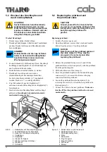
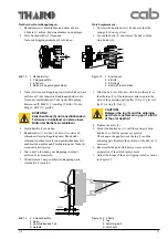
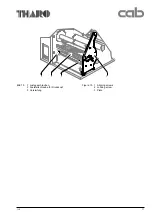
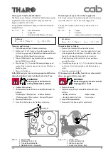
Bild 5
1 Kabelhalter auf Druckkopfbaugruppe
2 Feststellschraube für Druckkopf
3 Hebel zur Druckkopfverriegelung
4 Versteifung
5 Kopfplatte
6 Stecker für Signal
7 Stecker Leistung (Heizung)
8 Druckkopf
9 Schrauben
5.2
Replacing the printhead and
the printhead cable
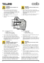
CAUTION!
Ground yourself to the chassis before
you remove or install the printhead. This
will prevent a static discharge from your
body through the printhead to
ground.
Replacing printhead:
1. Switch off printer, open cover.
2. Open the printhead , remove label stock and transfer
ribbon from the printer. Close the printhead.
NOTICE!
Note the loop of the printhead cables at
the cable clamp (1) ! They must be
arranged in the same manner after
replacing the printhead!
3. Release the printhead fixing screw (2) and lift the
printhead. Remove the head plate (5) with the printhead
from the positioning pins.
4. Pull both cables out of the clamp (1).
5. Move the printhead slightly to the front until the plug
connectors (6,7) are accessible. Remove the plug
connectors from the printhead.
6. Loosen the printhead from the head plate (5) by
removing the screws (9). Attach the new printhead to
the head plate (5).
7. Connect the cables to the new printhead. Make sure
that the PCB at the printhead will not be stressed
mechanically.
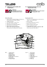
Figure 5 1 Cable holder on print head unit
2 Printhead fixing screw
3 Printhead locking lever
4 Plate
5 Head plate
6 Plug for signal
7 Plug for heating
8 Print head
9 Screws
Содержание A8
Страница 75: ...Index 1 00 02 29 A 8 B Anlage B Blockschaltbild Appendix B Block Diagram ...
Страница 85: ...Index 1 00 02 29 A 8 D1 Anlage D Belegungsplan Leiterplatte A8 Appendix D Layout Diagram PCB A8 ...
Страница 87: ...Index 1 00 02 29 A 8 E Anlage E Steckerplan A8 Appendix E Connector Diagram A8 ...
Страница 91: ...A 8 F4 ...

