45
A 8
6.6
Abgleich der Transferbandlicht-
schranke
Der Abgleich der Transferbandlichtschranke erfolgt über
das interne Setup (siehe Abschnitt 3.5).
6.7
Abgleich der Etikettenlichtschranke
Der Abgleich der Etikettenlichtschranke erfolgt über das
interne Setup (siehe Abschnitt 3.5).
6.8
Abgleich der Spendelichtschranke
(Option)
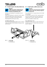
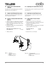
1. Gehäuse des Steckers (3) aufschrauben (2 Schrauben).
2. Spendelichtschranke (4) am Drucker montieren und
Stecker (3) in Peripherieschnittstelle (5, Bild 1) stecken.
3. Drucker einschalten.
4. Spannung am Lötauge (2) messen und bei Bedarf mit
Regler R1 (1) einstellen:
Etikett unter der Lichtschranke (4): U < 1,6V
Lichtschranke frei:
U > 3,5V
5. Gehäuse montieren.
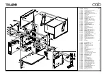
Bild 23
1 Regler R1
2 Lötpunkt für Messung
3 Stecker
4 Spendelichtschranke
Figure 23
1 Potentiometer R1
2 Terminal point for measurement
3 Plug
4 Present sensor
1
3
2
4
6.6
Adjusting the Transfer Ribbon Sensor
The transfer ribbon sensor is adjsuted by using the internal
setup (chapter 3.5).
6.7
Adjusting the Label Edge Sensor
The label edge sensor is adjsuted by using the internal
setup (chapter 3.5).
6.8
Adjusting the Present Sensor
(Option)
1. Remove 2 screws from the cover of the plug (3).
2. Mount the present sensor (4) at the printer and connect
the plug (3) to the peripheral port (5, fig. 1)
3. Switch on the printer.
4. Measure the voltage at the terminal point (2) and adjust
it using control R1 (1) if necessary:
Label under sensor (4):
U < 1,6V
Sensor free:
U > 3,5V
5. Reassemble the cover of the plug.
Содержание A8
Страница 75: ...Index 1 00 02 29 A 8 B Anlage B Blockschaltbild Appendix B Block Diagram ...
Страница 85: ...Index 1 00 02 29 A 8 D1 Anlage D Belegungsplan Leiterplatte A8 Appendix D Layout Diagram PCB A8 ...
Страница 87: ...Index 1 00 02 29 A 8 E Anlage E Steckerplan A8 Appendix E Connector Diagram A8 ...
Страница 91: ...A 8 F4 ...


