28
A 8
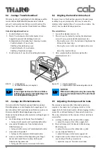
9. Push the cable to be replaced through the opening (13)
and thread the new cable.
10. Connect the plug of the new cable at the printhead.
Make sure that the PCB at the printhead will not be
stressed mechanically. Connect the cable at the PCB
A8.
CAUTION!
Positioning pins must snap in on both
sides !
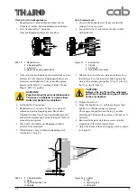
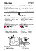
11. Carefully slide the head plate with the printhead onto
the positioning pins. Make sure that the head plate is
correctly set into the positioning pins, then tighten the
printhead fixing screw (2) slightly by hand. Note that
the printhead fits tightly in the bracket across the entire
bracket.
12. Close the printhead by turning the lever (3) counter-
clockwise. Thighten the printhead fixing screw (2). Do
not over-tighten the screw.
13. Attach both printhead cables at the cable clamp (1).
14. Perform a test print. Adjust the printhead if necessary.
Normally the positioning pins effect that the printhead
will be placed correctly. However, if the printhead
performs poorly, some adjustment may be necessary.
13
10
11
12
9. Zu wechselndes Kabel durch die Öffnung (13)
schieben und neues Druckkopfkabel einfädeln.
10. Stecker des neuen Kabels am Druckkopf aufstecken,
dabei die Druckkopf-Leiterplatte nicht mechanisch
beanspruchen. Stecker des neuen Kabels auf die
Leiterplatte A8 aufstecken.
ACHTUNG!
Positionierungsstifte müssen bei
Montage beidseitig einrasten!
11. Kopfplatte mit Druckkopf in die Positionierstifte
einsetzen. Sicherstellen, dass der Druckkopf richtig in
den Stiften geführt ist, dann Feststellschraube
(2, Bild 5) mit Hand leicht anziehen.
Dabei auf eine gute Anlage des Druckkopfes an die
Halterung über die gesamte Fläche achten.
12. Druckkopf mit Hebel (3, Bild 5) verriegeln und
Feststellschraube (2, Bild 5) festschrauben.
13. Beide Druckkopfkabel im Kabelhalter (1, Bild 5)
fixieren und Schlaufe auf dem Druckkopf ablegen.
14. Testdruck erzeugen und bei Bedarf Kopfjustierung
vornehmen.
Die Positionierstifte positionieren den Druckkopf
automatisch. Wenn der Druckkopf jedoch mangelhaft
arbeitet, kann ein Justieren erforderlich werden.
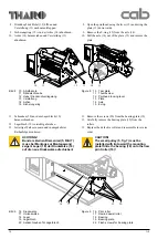
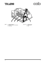
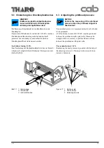
Bild 6
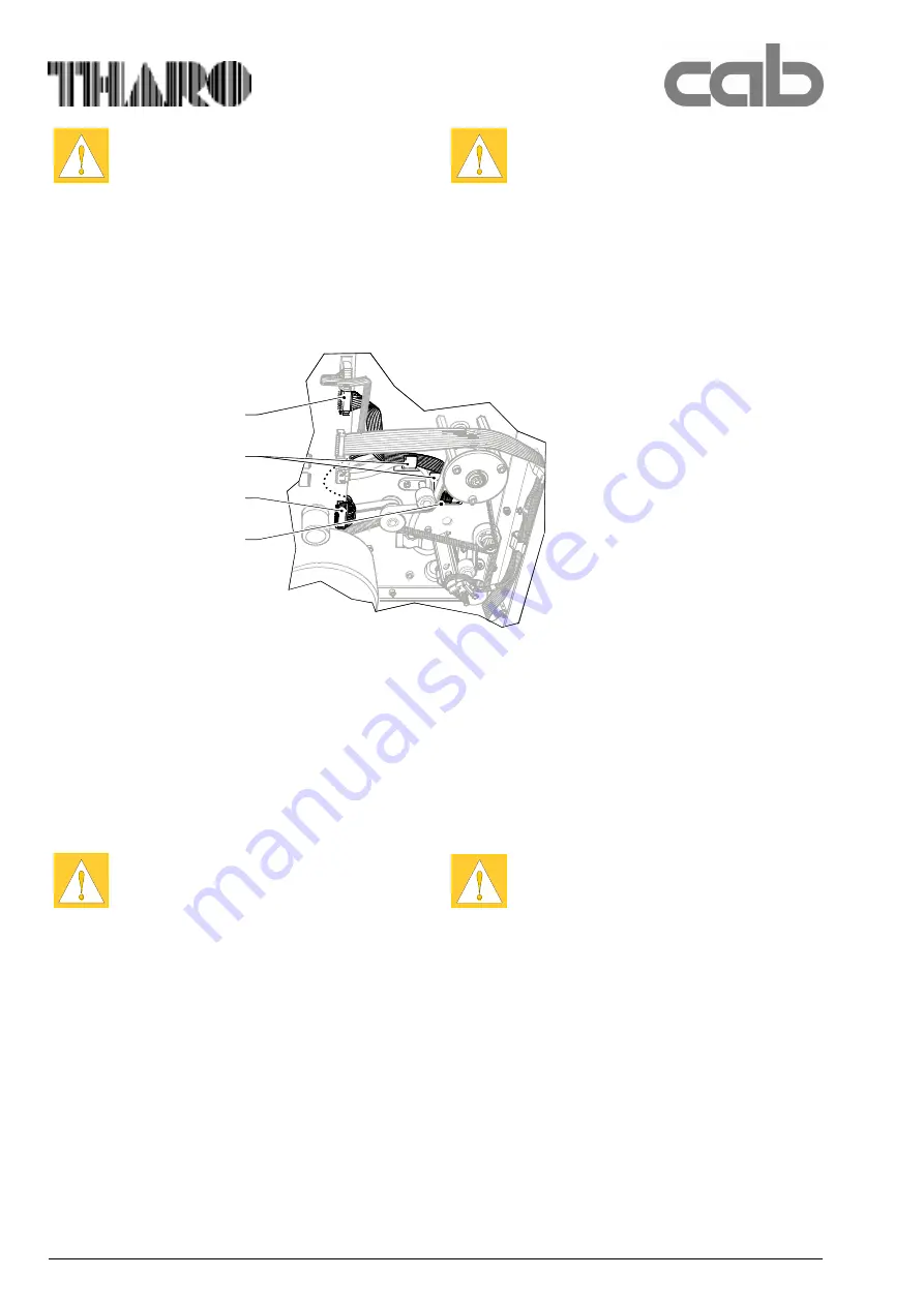
10 Stecker für Steuerung
11 Kabelhalter
12 Stecker Leistung (Heizung)
13 Öffnung in der Montagewand
Figure 6 10 Plug for signal
11 Cable holder
12 Plug for heating
13 Opening in assembly plate
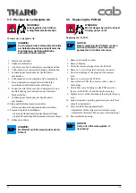
ACHTUNG!
Oberfläche des Druckkopfes nicht
zerkratzen!
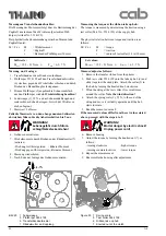
6. Stecker (6, Bild 5) oder (7, Bild 5) des auszu-
tauschenden Druckkopfkabels am Druckkopf
vorsichtig abhebeln. Druckkopf-Leiterplatte dabei
nicht mechanisch beanspruchen!
7. Kabel aus den Kabelhaltern (1, Bild 5) und (11)
herausnehmen.
8. Stecker (10) oder (12) von der Leiterplatte A8
abhebeln.
CAUTION!
Handle the printhead carefully to avoid
scratching!
6. Remove the plug connector (6 or 7, fig.5) of the
defective cable from the printhead. Make sure that the
PCB at the printhead will not be stressed
mechanically.
7. Pull the defective cable out of the clamps (1) and (11).
8. Remove the plug (10 or 12) from the PCB A8.
Содержание A8
Страница 75: ...Index 1 00 02 29 A 8 B Anlage B Blockschaltbild Appendix B Block Diagram ...
Страница 85: ...Index 1 00 02 29 A 8 D1 Anlage D Belegungsplan Leiterplatte A8 Appendix D Layout Diagram PCB A8 ...
Страница 87: ...Index 1 00 02 29 A 8 E Anlage E Steckerplan A8 Appendix E Connector Diagram A8 ...
Страница 91: ...A 8 F4 ...


