43
A 8
Messung am Etikettenabwickler:
Die Messung des Moments erfolgt über die Bestimmung der
Zugkraft an einem auf den Wickler aufgesteckten Prüf-
körper (Artikel-Nr. 553 9223).
Der physikalische Zusammenhang zwischen Moment und
Zugkraft lautet:
M = F x r
M
= Wickelmoment
F
= Zugkraft
r
= Radius des Prüfkörpers (30 mm)
Sollwerte :
M
Ab
= 15 - 16 Ncm
®
F
Ab
= 5 - 5,3 N
Messung und Justage :
1. Etiketten aus dem Drucker entnehmen.
2. Kappe (10) abziehen.
3. Prüfkörper 553 9223 auf den Etikettenabwickler (8)
stecken.
HINWEIS!
Der in den Prüfkörper eingelassene Stift
muss in die Aussparung des Wicklers
greifen!
4. Die am Prüfkörper (9) angebrachte Schnur mehrfach
um den Prüfkörper wickeln.
5. Federwaage (1), 25 N, an das Schnurende hängen und
senkrecht nach oben bewegen, bis sich der Wickler zu
drehen beginnt.
6. Messwert F ablesen.
Falls die Messwerte von den oben genannten Sollwerten
abweichen, führen Sie die Arbeitsschritte 7 und 8 aus.
7. Wickelmomente durch Drehen an der Rändelmutter
(11) justieren:
- Drehung im Uhrzeigersinn
- höheres Moment
- Drehung gegen Uhrzeigersinn - kleineres Moment
8. Messung wiederholen.
9. Nach Ende der Justage Kappe montieren
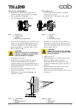
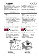
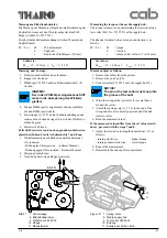
Bild 21
1 Federwaage
8 Etikettenabwickler
9 Prüfkörper 553 9223
10 Kappe
11 Rändelmutter
Figure 21 1 Spring scale
8 Media supply hub
9 Test collar 553 9223
10 End cap
11 Knurled nut at the clutch
5-5,3 N
1
8
9
11
10
Measuring the torque at the media supply hub:
The torque is measured by determining the traction using a
test collar (Part. No. 553 9223) at the supply hub.
The physical relation between torque and traction is as
follows:
M = F x r
M
= torque
F
= traction
r
= radius of test collar (1.2 in/30 mm)
Set values :
M
supply
= 15 - 16 Ncm
®
F
supply
= 5 - 5.3 N
Measure/adjust as follows:
1. Remove the labels from the printer.
2. Remove the end cap (10).
3. Push test collar 553 9223 onto the supply hub (8).
NOTICE!
The pin at the test collar must snap into
the groove of the hub!
4. Wind the string at the test collar (9) several times
around the collar.
5. Attach the spring scale (1), 25 N, to the end of the
string and move it vertically upwards until the hub
starts to rotate.
6. Read the measured value F.
If the measured values differ from the set values stated
above, proceed with the steps 7 and 8.
7. Adjust the torque by turning the knurled nut (11) as
follows:
- turning clockwise
- higher torque
- turning counterclockwise
- lower torque
8. Repeat the measurement.
9. Reassemble the end cap after adjustment.
Содержание A8
Страница 75: ...Index 1 00 02 29 A 8 B Anlage B Blockschaltbild Appendix B Block Diagram ...
Страница 85: ...Index 1 00 02 29 A 8 D1 Anlage D Belegungsplan Leiterplatte A8 Appendix D Layout Diagram PCB A8 ...
Страница 87: ...Index 1 00 02 29 A 8 E Anlage E Steckerplan A8 Appendix E Connector Diagram A8 ...
Страница 91: ...A 8 F4 ...

