


Page 31 of 106
INSTRUCTION, USE AND
MAINTENANCE MANUAL
GB
KENDO.30LIGHT-KENDO.30LIGHTFI
7105-M002-0_B
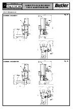
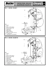
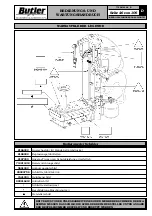
Fig. 12
Fig. 13
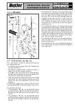
a
=621 mm
b
=440 mm
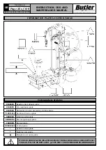
Fig. 11
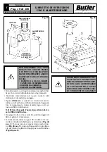
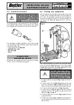
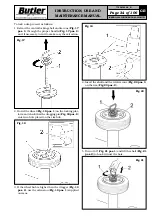
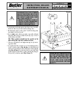
The holes in the solid floor must be about 10 cm deep
with a diameter of 8 mm.
The bolts (
Fig. 12 pos. 1
) must be inserted in the holes
and fully tightened
Before fixing completely the machine to the ground, flush
its rear part rotating the feet (
Fig. 13 Pos. 1
).
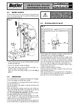
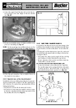
10.0 ANCHORING SYSTEM
The packed machine is fixed to a pallet by support feet.
Such feet also fix the machine to the ground through
anchor small blocks as shown in
Fig. 12
.
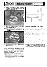
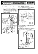
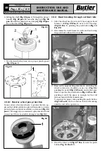
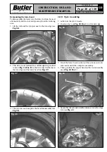
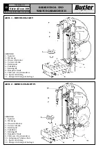
7. To assembly again the lateral guard (
Fig. 11 pos. 1-2
)
of the machine.
NOTE:
after the assembly, to check the right position of
the tools. To lock the rim on the chuck center.
With the bead breaker arm, to check that the
distance between the roll and the rim edges (up-
per and lower) is the same. To repeat the all the
procedures starting from the point one if the dis-
tance is not the same.