background image

7 | Parameter Overview

16 / 56

0870166596_MV0040-0080C-D_PCI_A0004_IM_de_MD

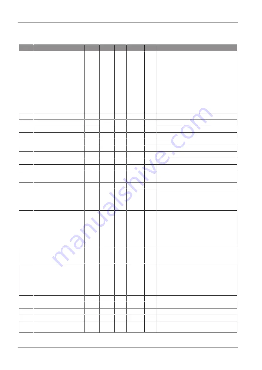
7.4 Advanced Settings: Menu PAR G2

Code Parameter

Min.

Max.

Unit Default ID

Description

P2.1

Start/Stop logic

0

3

0

300

Logic = 0:

Start sgn 1 = Start forward
Start sgn 2 = Start backward

Logic = 1:

Start sgn 1 = Start
Start sgn 2 = Reverse

Logic = 2:

Start sgn 1 = Start pulse
Start sgn 2 = Stop pulse

Logic = 3:

Start sgn 1 = Start forward (edge)
Start sgn 2 = Start backward (edge)

P2.2

Preset speed 1

0

P1.2

Hz

10

105

Multistep speed 1

P2.3

Preset speed 2

0

P1.2

Hz

15

106

Multistep speed 2

P2.4

Preset speed 3

0

P1.2

Hz

20

126

Multistep speed 3

P2.5

Preset speed 4

0

P1.2

Hz

25

127

Multistep speed 4

P2.6

Preset speed 5

0

P1.2

Hz

30

128

Multistep speed 5

P2.7

Preset speed 6

0

P1.2

Hz

40

129

Multistep speed 6

P2.8

Preset speed 7

0

P1.2

Hz

50

130

Multistep speed 7

P2.9

Acceleration time 2

0.1

3000

s

10

502

Time from 0 to maximum frequency

P2.10 Deceleration time 2

0.1

3000

s

10

503

Time from maximum frequency to 0

P2.11 Accel 1 to Accel 2 

transition frequency

0

P1.2

Hz

0

527

Threshold for auto change 
Accel 1 to Accel 2

P2.13 S ramp shape

0

10

s

0

500

Rounded speed profile

P2.14 Control place 2

0

2

0

1806 Alternative control place:

0 = I/O terminals
1 = Keypad
2 = Fieldbus

P2.15 Frequency reference

source 2

0

5

2

1820 Selection of reference source 2:

0 = Analogue input 1
1 = Analogue input 2
2 = PID reference
3 = Motor potentiometer
4 = Keypad
5 = Fieldbus

P2.16 Motor potentiometer

ramp

1

50

Hz/s 5

331

Rate of change in the motor poten-
tiometer reference when increased or 
decreased.

P2.17 Motor potentiometer 

reference memory

0

2

0

367

Motor potentiometer frequency refer-
ence 
reset logic:
0 = No reset
1 = Reset if stopped or powered down
2 = Reset if powered down

P2.18 Skip range 1 low limit

0

P1.2

Hz

0

509

0 = Not used

P2.19 Skip range 1 high limit

0

P1.2

Hz

0

510

0 = Not used

P2.20 Skip range 2 low limit

0

P1.2

Hz

0

511

0 = Not used

P2.21 Skip range 2 high limit

0

P1.2

Hz

0

512

0 = Not used

P2.22 Stop button active

0

1

0

114

0 = Limited function of stop button
1 = Stop button always enabled

Содержание Mink MV 0040 C

Страница 1: ...instruction manuals service kits Pump Control Instructions MINK mit Frequenzumrichter MV 0040 C MV 0060 C MV 0080 C MV 0040 D MV 0060 D MV 0080 D 0870166596 A0004_de Original instructions Modifications reserved 22 06 2021 ...

Страница 2: ...cting to the Vacuum Pump 12 7 Parameter Overview 13 7 1 Overview I O Connections 13 7 2 Monitoring Group Menu MON 13 7 3 Basic Parameters Menu PAR G1 14 7 4 Advanced Settings Menu PAR G2 15 7 5 Analogue Inputs Menu PAR G3 17 7 6 Digital Inputs Menu PAR G4 17 7 7 Digital Outputs Menu PAR G5 19 7 8 Analogue Outputs Menu PAR G6 19 7 9 Group Supervisions Menu PAR G7 20 7 10 Motor Control Menu PAR G8 2...

Страница 3: ...Table of Contents 0870166596_MV0040 0080C D_PCI_A0004_IM_de_MD 3 8 9 Fieldbus 39 8 10 PID Control 40 9 Troubleshooting 42 9 1 Fault Tracing 42 10 Basic Connection Examples 43 ...

Страница 4: ...has been designed and manufactured according to state of the art meth ods Nevertheless residual risks may remain This instruction manual highlights po tential hazards where appropriate Safety notes and warning messages are tagged with one of the keywords DANGER WARNING CAUTION NOTICE and NOTE as follows DANGER indicates an imminent dangerous situation that will result in death or serious injuries ...

Страница 5: ... of Delivery Keypad incl 1 m cable and bracket for wall mounting Cable feed through 2 2 Application The Keypad is intended for Parametrisation of the variable frequency drive Control e g locking and releasing Display of various process values of the following machines MINK MV 0040 C D MINK MV 0060 C D MINK MV 0080 C D ...

Страница 6: ...e_MD 3 Installation Keypad The back side of the keypad is equipped with magnets to fix magnetically the manual control unit either on the vacuum pump or on another part Remove the bracket for wall mounting Magnetically fix the keypad on desired place 3 1 Wall Mounting ...

Страница 7: ...lectrical installation work must only be executed by qualified personnel TB CF Open the cover of the terminal box TB Pull the cable of the keypad through the supplied cable feed through CF Screw in the cable feed through CF Connect the coupling device of the keypad with the intended interface on the va cuum pump Close the cover of the terminal box TB ...

Страница 8: ... Move cursor right Scroll menu down decrease value Scroll menu up increase value Change control place Enter active level item Confirm selection Move backward in menu Exit edit mode Reset faults Mover cursor left Stop key Start key 4 2 Display Overview Hz 140 00 Operation status Error Control place Direction Menu ...

Страница 9: ...h the arrow keys LEFT RIGHT if the value is numerical Confirm changes with OK key or ignore change by returning to previous level with BACK RESET key 4 5 Remote and Local Control Place The LOC REM key is intended for switching between remote control place and local control place The control place is the source of control where the frequency inverter can be started and stopped Every control place h...

Страница 10: ...nt No of the fault Id Sub code of the fault Some faults have a sub code for more de tailed identification 0 Fault without sub code d Day Day according to the operating hours counter H Hour Hour according to the operating hours counter M Minute Minute according to the operating hours counter The fault remains active unless the fault will be reset by BACK RESET key by a reset signal on terminal 10 o...

Страница 11: ... Delivery USB Stick with appreciate PC software parameter description and software instruc tions Connection cable 5 2 Application The Parametrisation Kit is intended for Parametrisation of the frequency inverter Controlling Indication of values Saving of set of parameter of the following machines MINK MV 0040 C D MINK MV 0060 C D MINK MV 0080 C D ...

Страница 12: ...r Notebook 6 1 Connecting to the Vacuum Pump DANGER Live wires Risk of electrical shock Electrical installation work must only be executed by qualified personnel TB CF Open the cover of the terminal box TB Pull the cable of the keypad through the supplied cable feed through CF Screw in the cable feed through CF Connect the coupling device of the keypad with the intended interface on the va cuum pu...

Страница 13: ...ailable 14 Digital In 4 Maintenance counter reset 13 Digital Out Ground 5 Ground 4 Analogue In 2 Busch pressure transmitter 4 20 mA 0 2 bar 10 Digital In 3 Fault reset 9 Digital In 2 open speed control contact pressure control 8 Digital In 1 open stop contact start 7 Digital Ground 6 24 V Out 3 Ground 2 Analogue In 1 speed control 0 V 0 mA n 1200 min min 1 10 V 20 mA nmax setpoint pressure control...

Страница 14: ...or temperature 9 Calculated motor temperature V1 9 DC link voltage V 7 DC link voltage V1 10 Unit temperature C 8 Heat sink temperature V1 11 Board temperature C 1825 Power board temperature V1 12 Analogue input AI 1 13 Analogue input AI 1 V1 13 Analogue input AI 2 14 Analogue input AI 2 V1 15 Analogue output 26 Analogue output V1 18 DI 1 DI 2 DI 3 15 Digital inputs status V1 19 DI 4 DI 5 DI 6 16 ...

Страница 15: ...UnMotor Note also used connection Delta Star P1 7 Motor nominal frequency 8 320 Hz 140 111 According motor data P1 8 Motor nominal speed 24 20000 rpm 4200 112 According motor data P1 9 Motor nominal current 0 2xIH 2xIH A 0 113 According motor data P1 10 Motor Cos Phi 0 30 1 0 93 120 According motor data P1 11 Control Place 0 2 0 125 Run and direction control 0 I O terminals 1 Keypad 2 Fieldbus P1 ...

Страница 16: ... 0 1 3000 s 10 503 Time from maximum frequency to 0 P2 11 Accel 1 to Accel 2 transition frequency 0 P1 2 Hz 0 527 Threshold for auto change Accel 1 to Accel 2 P2 13 S ramp shape 0 10 s 0 500 Rounded speed profile P2 14 Control place 2 0 2 0 1806 Alternative control place 0 I O terminals 1 Keypad 2 Fieldbus P2 15 Frequency reference source 2 0 5 2 1820 Selection of reference source 2 0 Analogue inp...

Страница 17: ...5535 Current version 1904 Version of the set of parameter Visibility of the group depends on P1 16 7 5 Analogue Inputs Menu PAR G3 Code Parameter Min Max Unit Default ID Description P3 1 AI1 signal range 0 1 0 379 0 0 10 V 0 20 mA 1 2 10 V 4 20mA P3 2 AI1 custom min 100 100 0 380 Custom range min setting 20 4 20 mA 2 10 V P3 3 AI1 custom max 100 300 100 381 Custom range max setting P3 4 AI1 filter...

Страница 18: ...8 Preset speed B0 0 6 0 419 Binary selector for preset speeds 0 7 See P2 1 for function See P4 1 for selections P4 9 Preset speed B1 0 6 0 420 Binary selector for preset speeds 0 7 See P2 1 for function See P4 1 for selections P4 10 Preset speed B2 0 6 0 421 Binary selector for preset speeds 0 7 See P2 1 for function See P4 1 for selections P4 11 Select Accel Decel 2 0 6 0 408 Activates ramp 2 See...

Страница 19: ...eneral fault inverted 5 Warning 6 Reversed 7 At speed 8 Output frequency supervision 9 Output current supervision 10 Analogue input supervision 11 Fieldbus 1 12 Fieldbus 2 13 External brake P5 2 Relay output 2 content 0 14 3 314 See P5 1 P5 3 Digital Output 1 content 0 14 1 312 See P5 1 P5 4 Relay output 1 on delay 0 320 s 0 458 ON delay for relay P5 5 Relay output 1 off delay 0 320 s 300 459 OFF ...

Страница 20: ...quency supervision 1 0 12 0 315 0 Not used 1 Low limit 2 High limit P7 2 Frequency supervision value 0 P1 2 Hz 0 316 Output frequency supervision threshold P7 3 Current supervision 0 2xIH A 0 1811 Current supervision threshold P7 4 Analogue input supervision signal 0 2 0 356 0 AI1 1 AI2 P7 5 Analogue input supervision ON level 0 100 80 357 ON threshold AI supervision P7 6 Analogue input supervisio...

Страница 21: ...Switching frequency 1 5 16 kHz 8 Motor noise can be minimized by using a high switching frequency Increasing the switching frequency reduces the capacity of the drive It is recommended to use a lower frequency when the motor cable is long to minimize capacitive currents in the cable P8 9 Brake chopper 0 2 0 0 Disable 1 Enable in RUN 2 Enable in READY P8 10 Brake chopper threshold 600 900 V 0 DC li...

Страница 22: ...ult 3 Warning if start active 4 Fault if start active P9 2 4 mA fault detection time 0 10 s 0 5 1430 Time limit P9 3 Earth fault protection 0 2 2 703 0 No action 1 Warning 2 Fault P9 4 Motor stall protection 0 2 2 709 See P9 3 P9 5 Motor stall delay 0 300 s 5 711 Maximum allowed time for stall stage P9 6 Motor stall minimum frequency 0 1 320 Hz 15 712 For a stall state to occur the output fre quen...

Страница 23: ...1 65535 h 1902 Determine the service time 7 12 Autoreset Menu PAR G10 Code Parameter Min Max Unit Default ID Description P10 1 Automatic fault reset 0 1 1 731 0 Disabled 1 Enabled P10 2 Wait time 0 1 10 s 0 5 717 Wait time before the first reset is ex ecuted P10 3 Trial time 0 60 s 30 718 When the trial time has elapsed and the fault is still active the drive will trip to fault P10 4 Automatic res...

Страница 24: ... mapped on PD3 See P11 1 P11 4 ProcessDataOut 4 selection 0 16 4 855 Variable mapped on PD4 See P11 1 P11 5 ProcessDataOut 5 selection 0 16 5 856 Variable mapped on PD5 See P11 1 P11 6 ProcessDataOut 6 selection 0 16 3 857 Variable mapped on PD6 See P11 1 P11 7 ProcessDataOut 7 selection 0 16 6 858 Variable mapped on PD7 See P11 1 P11 8 ProcessDataOut 8 selection 0 16 7 859 Variable mapped on PD8 ...

Страница 25: ...ID controller D time 0 10 s 0 132 If this parameter is set to 1 00 second a change of 10 in the error value during 1 00 s causes the controller output to change by 10 P12 1 0 Error value inversion 0 1 1 340 0 Normal Feedback Set Point in crease PID output 1 Inverted Feedback Set Point de crease PID output P12 1 1 PID error limit 0 100 100 1812 Limit on error P12 1 2 Sleep frequency 0 P1 2 Hz 42 10...

Страница 26: ...sion 838 V1 7 System load 839 V3 1 MWh counter 827 V3 2 Power on day counter 828 V3 3 Power on hour counter 829 V3 4 RUN day counter 840 V3 5 RUN hour counter 841 V3 6 Fault counter 842 V3 7 Panel parameter set status monitor Hidden when Computer is connected P4 2 Restore factory defaults 0 1 0 831 1 Restore factory defaults for all para meters P4 3 Password 0 9999 0 832 P4 4 Time keypad backlight...

Страница 27: ...1 P1 11 Control Place Run and direction control A second control place is programmable in P2 10 0 I O Terminals 1 Keypad 2 Fieldbus P1 12 Frequency Reference Source Define the source of frequency reference A second reference source is program mable in P2 10 0 Analogue input AI1 1 Analogue input AI2 2 PID control 3 Motor potentiometer 4 Keypad 5 Fieldbus P1 13 Start Function 0 Ramping 1 Flying star...

Страница 28: ...rs P4 8 P4 9 and P4 10 binary code The values of the preset frequencies are automatically limited between the minimum and maximum frequen cies Required Action Activated Frequency P4 10 P4 9 P4 8 0 0 1 Preset speed 1 0 1 0 Preset speed 2 0 1 1 Preset speed 3 1 0 0 Preset speed 4 1 0 1 Preset speed 5 1 1 0 Preset speed 6 1 1 1 Preset speed 7 P2 10 Deceleration Time 2 Ramp 2 is activated through digi...

Страница 29: ...acceleration deceleration The acceleration time is determined with parameters P1 3 and P1 4 P1 3 P1 4 Hz t P2 13 P2 13 These parameters are used to reduce mechanical erosion and current spikes when the reference is changed P2 14 Control Place 2 Alternative Run and direction control Activated by digital input defined in P4 14 0 I O terminals 1 Keypad 2 Fieldbus P2 15 Frequency Reference Source 2 Al...

Страница 30: ... 22 Stop Button Active 0 Active only in keypad control mode 1 Always active P2 23 Keypad Reverse Effective when control is from panel 0 Forward 1 Backward P2 25 Quick Stop Deceleration Time Specific ramp time for quick stop To see description of P4 17 for details about the function P2 26 S Ramp Shape 2 See parameter P2 13 P2 28 Customer Password This parameter can lock all parameters by a password...

Страница 31: ...imum signal Effective when different than 0 P3 3 and P3 7 AI1 and AI2 Custom Max Customized value for maximum signal Effective when different than 100 P3 4 and P3 8 AI1 and AI2 Filter Time Low pass filter time constant to reduce noise When this parameter is given a value greater than 0 the function that filters out disturbances from the incoming analogue signal is activated Long filtering time mak...

Страница 32: ...alogue signal the frequency refer ence is at 50 of the set frequency range Max Frequency Min Frequency 2 With maximum analogue signal the frequency reference is at Max Frequency Green line shows the default settings of custom values Custom Min 0 and Cus tom Max 100 These settings provide a frequency range between Min and Max Frequency With minimum analogue signal the frequency reference is at Min ...

Страница 33: ...y Min Frequency 2 and with maximum analogue signal the frequency reference is at Min Frequency Blue line shows the inversion of the default settings of custom values Custom Min 100 and Custom Max 0 These settings provide a frequency range between the Min Frequency and the Max Frequency With minimum analogue signal the Fre quency Reference is Max Frequency while with the maximum level is Min Freque...

Страница 34: ...gue signal the frequency reference is at Max Frequency Min Frequency 2 Green line shows an example with Custom Min 100 and Custom Max 200 These settings provide a frequency range always at Min Frequency The frequency reference is at Min Frequency within the entire analogue signal range Orange line shows an example with Custom Min 0 and Custom Max 50 These settings provide a frequency range between...

Страница 35: ...Digital input high causes speed increase Motor potentiometer functionality is activated only with P1 12 3 or P2 15 3 P4 13 Motor Potentiometer Decrease Speed Digital input high causes speed reduction Motor potentiometer functionality is activ ated only with P1 12 3 or P2 15 3 P4 14 Select Control Place 2 Digital input high activates control place 2 P2 10 P4 15 Select Frequency Reference 2 Digital ...

Страница 36: ...d Digital Output DO1 Function for relays and digital output Selection Selection name Description 0 Not used 1 Ready Frequency inverter is ready to operate 2 Run Frequency inverter operates motor is running 3 General fault A fault trip has occurred 4 General fault inverted A fault trip has NOT occurred 5 General alarm 6 Reversed The reverse command has been selected 7 At speed The output frequency ...

Страница 37: ... 2 3 Motor speed Motor nominal speed 4 Motor current Motor nominal current 5 Motor torque Motor nominal torque absolute value 6 Motor power Motor nominal power absolute value 7 PID output 100 8 Fieldbus control 10000 P6 2 Analogue Output Minimum 0 0 V 1 2 V P6 3 Analogue Output Scale Scaling factor P6 4 Analogue Output Filter Time Time constant of low pass filter 8 7 Supervisions P7 1 Frequency su...

Страница 38: ...until the brake is opened P7 9 External Brake Close Frequency Limit The brake is closed when the start command is low and output frequency is below this threshold The brake is also closed whenever the drive is no more in RUN state P7 10 Process Source Select Monitor V1 24 can show a process value proportional to a variable measured by the drive Source variables are 0 PID actual value max 100 1 Out...

Страница 39: ... Wait Time Time after which the converter attempts to restart the motor automatically after the fault has been eliminated P10 3 Trial Time Total time for reset attempts P10 4 Automatic Reset Tries Trials attempted during time P10 3 P10 5 Start Function Start function after an automatic fault reset 0 Start with ramp 1 Flying start 2 As defined in P1 13 8 9 Fieldbus P11 1 to P11 8 ProcessDataOut 1 8...

Страница 40: ...11 12 FB Analogue Out Cntrl Selection Parameter defines the input process data coupled to analogue output control Selections as P11 9 8 10 PID Control Parameters of this group are hidden unless the regulator is used as frequency refer ence P1 12 2 or P2 15 2 P12 1 Set Point Source 0 Fixed set point 1 2 1 Analogue AI1 2 Analogue AI2 3 Fieldbus P12 2 and P12 3 PID Set Point 1 and 2 Programmable set ...

Страница 41: ... drive into sleep mode if the set point is reached and the out put frequency stays below the sleep limit for a longer time than set in the sleep delay P12 13 This means that the start command remains on but the run request is turned off When the PID error value goes below or above the wake up level depend ing on the set acting mode P12 10 the drive will activate the run request again if the start ...

Страница 42: ...les and motor 8 System fault Component fault malfunc tion Reset the fault and restart Should the fault re occur contact your Busch repre sentative 9 Undervoltage DC link voltage is under the voltage limits defined In case of temporary sup ply voltage break reset the fault and restart the AC drive Check the supply voltage If it is adequate an internal failure has oc curred Repair the vacuum pump Bu...

Страница 43: ...liary power sup ply are used by con sumers Check dip switch 1 correct is 0 52 Keypad commu nication fault The connection between the control keypad and the frequency converter is broken Check keypad connection and keypad cable 53 Fieldbus commu nication fault The data connection between the fieldbus mas ter and fieldbus board is broken Check installation and fieldbus master 54 Fieldbus interface e...

Страница 44: ...a digital input Speed pre setting Preset references PID control external sensor required 3 Operating via PC Interface converter cable optional Start and speed setting via PC software optional accessory 4 Operating via manual control unit optional Start and speed setting via manual control unit optional accessor y 5 Operating via Modbus Parameterization via PC or manua l control unit required Start...

Страница 45: ...arameter P4 15 from 2 to 0 Set desired frequency in parameter P2 2 P2 3 and P2 4 PID control external sensor required DI2 Set point AI1 0 10 V Actual value AI2 4 20 mA Remove bridge from terminal 1 2 Digital signal on terminal 9 Analog signal 0 10V on terminal 2 Analog signal 4 20mA on terminal 4 Potentiometer 1 10 kOhm Terminal 1 2 3 Potentiometer 1 10 kOhm Terminal 1 2 3 Pressure transmitter Ter...

Страница 46: ...eter P4 8 from 0 to 5 Set desired frequency in parameter P2 2 Digital signal on terminal 9 Change parameter P4 9 from 0 to 2 Change parameter P4 15 from 2 to 0 Set desired frequency in parameter P2 2 P2 3 and P2 4 PID control external sensor required DI1 DI2 Set point AI1 0 10 V Actual value AI2 4 20 mA Remove Bridge from terminal 1 2 Digital signal on terminal 8 Digital signal on terminal 9 Analo...

Страница 47: ...ed Components Example 3 Operating via PC Interface converter cable optional Start and speed range via PC Software Serial Interface Remove terminal strip bridges in order to disable the Autostart function Connect converter cable Activate control in PC Software USB Converter Cable Option PC Software Converter cable connected Remove terminal strip ...

Страница 48: ...tart function Connect manual control unit Change parameter P1 11 from 0 to 1 Change parameter P1 12 from 0 to 4 Manual control unit Busch Option Remove terminal strip Attention We highly recommend to record parameter changes The manual control unit has no storage function and will not show the executed alterations of the pump settings Before disconnecting the manual control unit from the drive aft...

Страница 49: ...ation USB converter cable Option or manual control unit Option Operating via Modbus Para meterisation via PC or manual control unit PID Control Setpoint setting via Modbus Set point Transmission of bus protocol via RS 485 Interface Actual value AI2 4 20 mA Remove Bridges Analog signal 4 20mA on terminal 4 Change parameter P1 11 from 0 to 2 Change parameter P1 12 from 0 to 2 Change parameter P12 1 ...

Страница 50: ...erminal 5 GND brown I p A Determination actual value source Connect pressure transmitter to analogue input 2 4 20mA Pressure transmitter 0 2000 mbar abs optional accessory Alternative also in combination Pressure transmitter two wire technique Connection to terminal 5 eliminated Pressure transmitter 2 10 V Change DIP switch 3 from 0 to 1 Pressure transmitter with different measuring range Paramete...

Страница 51: ...lternative Programmed actual value Change parameter P12 1 from 1 to 0 setpoint source AI1 programmed setpoint 1 2 Change parameter P12 2 programmed setpoint 1 to desired percentage 10 100 mbar Alternative Connect external analogue signal 4 20 mA to analogue input Connect external signal line Change DIP switch 2 from 1 to 0 Change parameter P3 1 from 0 to 1 Signal range 0 10 V 0 20 mA 2 10 V 4 20 m...

Страница 52: ...fication Effect Stronger response to control deviation Stronger oscillation tendency of the system Implementation Increase parameter P12 7 from 350 Alteration Decrease the integration time constant Effect Faster response to control deviation Oscillation tendency instability of the system Implementation Decrease parameter P12 8 from 0 5s Example MV 0040 C 80 liter vessel Parameter P12 7 500 and P12...

Страница 53: ...mentation Change parameter P12 13 from 5s to desired value Alteration Change of Wake up level Effect Chang of set point deviation at which the pump will be restarted Implementation Change of parameter P12 14 from 5 to desired value Example MV 0040 C 80 liter vessel pressure set po int 200 mbar Parameter P12 13 2s and P12 14 1 reduced fall below pressure set point since the pump switch off more qui...

Страница 54: ...40 mbar P12 3 approx 20 approx 200 mbar pump 2 P12 1 0 setpoint setting with fixed setpoint 1 2 P12 2 approx 20 approx 200 mbar P12 3 approx 14 approx 140 mbar Both pumps will start pump 2 will switch off after pressure drops below 200 mbar and after the sleep time pump 1 will control down to 140 mbar If the value of 200 mbar is achieved due to exeeding vacuum demand and wake up level is passed pu...

Страница 55: ...Note ...

Страница 56: ...o busch it Japan info busch co jp Korea busch busch co kr Malaysia busch busch com my Mexico info busch com mx Netherlands info busch nl New Zealand sales busch co nz Norway post busch no Peru info busch com pe Poland busch busch com pl Portugal busch busch pt Romania office buschromania ro Russia info busch ru Singapore sales busch com sg South Africa info busch co za Spain contacto buschiberica ...

Отзывы: