3 - 39
Needle-presser unit
Main unit
Assembly
3
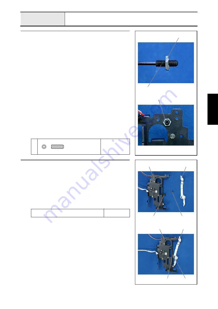
Lock nut attachment
1. Attach the screw
1
to the lock nut
1
.
*Key point
• Screw
1
the screw in half way.
2. Attach the screw
1
to the base holder assy..
*Key point
• Tighten the screw until the lock nut
1
contacts the base
holder assy..
1
1
1
1
Set Screw, Socket (CP)
M4X12
4
Thread release lever attachment
1. Apply a bead of EPNOC AP (N) 0 to the caulking shaft
2
of the base
holder assy.
1
.
2. Attach the thread release lever
3
and the spring
4
to the caulking shaft
2
of the base holder assy.
1
, and then attach the retaining ring (CS4).
*Key point
• Position the tip of the spring at the top, and align the spring
with the hole on the thread release lever
3
.
• Secure 0.2 mm between the thread release lever
3
and the
base holder
5
.
Apply EPNOC AP (N) 0 to the caulking shaft of the
base holder assy..
Bead
XC8387***
1
2
4
3
1
4
3
Retaining ring CS4
Содержание HS-3000
Страница 1: ......
Страница 2: ......
Страница 3: ......
Страница 9: ...vi ...
Страница 16: ...2 1 2 Disassembly Main parts 2 2 Feed unit 2 22 Needle presser unit 2 30 ...
Страница 17: ...2 2 Main parts Main parts location diagram Main unit ...
Страница 37: ...2 22 Feed unit location diagram Main unit ...
Страница 45: ...2 30 Needle presser unit location diagram Main unit ...
Страница 55: ...3 2 Main parts Main parts location diagram Main unit ...
Страница 77: ...3 24 Main unit Main parts 36 Accessory table attachment 1 Attach the accessory table 1 1 ...
Страница 78: ...3 25 Assembly Feed unit Feed unit location diagram Main unit ...
Страница 90: ...3 37 Assembly Needle presser unit Needle presser unit location diagram Main unit ...
Страница 163: ...7 12 ...
Страница 164: ......


