


2 - 6
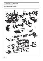
Main unit
Main parts
5
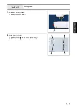
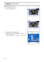
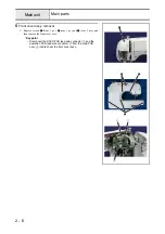
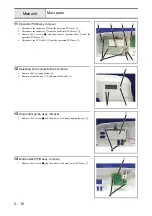
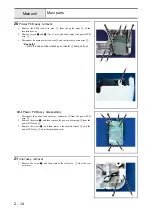
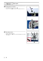
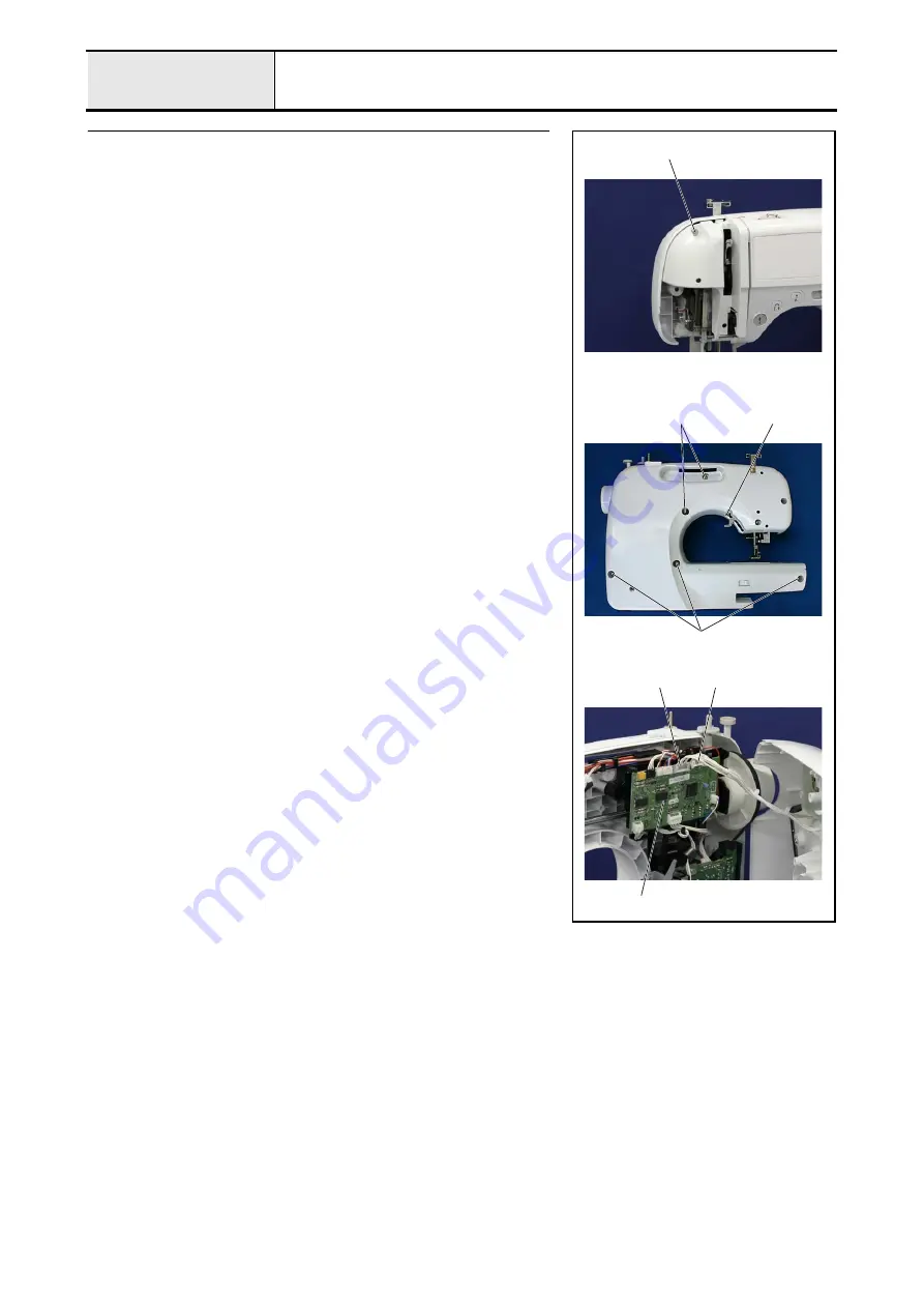
Front cover assy. removal
1. Remove screws
1
(front, 1 pc.),
2
(rear, 1 pc.), and
3
(rear, 5 pcs.), and
then remove the front cover assy..
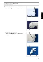
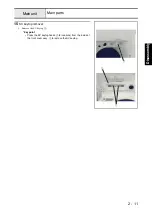
*Key point
• Disconnect the SSVR PCB lead wire connector
1
and the
operation PCB lead wire connector
2
from the main PCB
assy.
3
located near the front cover assy..
3
3
2
1
3
2
1
Содержание HS-3000
Страница 1: ......
Страница 2: ......
Страница 3: ......
Страница 9: ...vi ...
Страница 16: ...2 1 2 Disassembly Main parts 2 2 Feed unit 2 22 Needle presser unit 2 30 ...
Страница 17: ...2 2 Main parts Main parts location diagram Main unit ...
Страница 37: ...2 22 Feed unit location diagram Main unit ...
Страница 45: ...2 30 Needle presser unit location diagram Main unit ...
Страница 55: ...3 2 Main parts Main parts location diagram Main unit ...
Страница 77: ...3 24 Main unit Main parts 36 Accessory table attachment 1 Attach the accessory table 1 1 ...
Страница 78: ...3 25 Assembly Feed unit Feed unit location diagram Main unit ...
Страница 90: ...3 37 Assembly Needle presser unit Needle presser unit location diagram Main unit ...
Страница 163: ...7 12 ...
Страница 164: ......