


2-31
Confidential
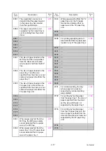
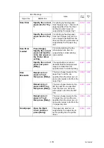
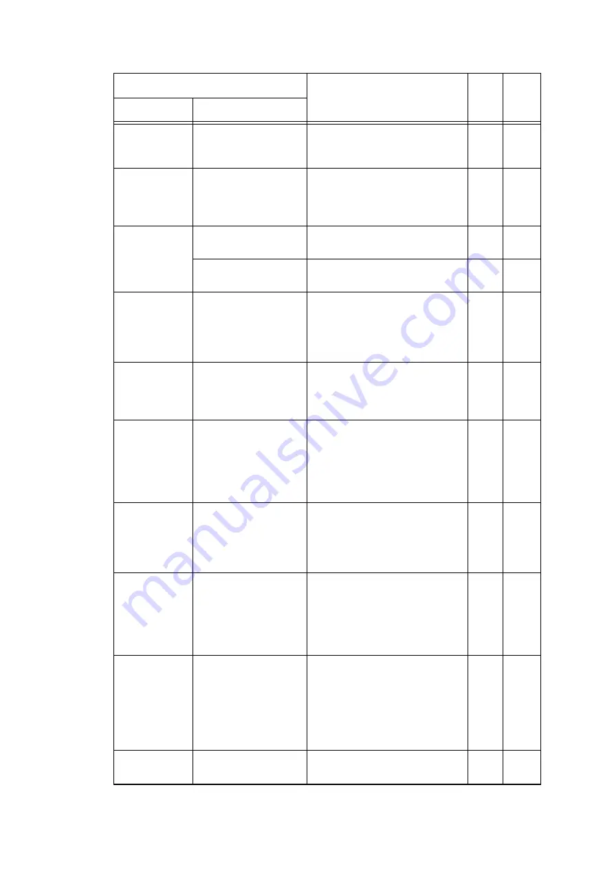
Drum !
-
Electric discharge that may be
caused by dirt on the corona wire
of the drum unit was detected.
Drum Stop
Replace the Drum
Unit.
Electric discharge was detected
when the number of the drum unit
rotations had become more than
twice of the upper limit.
Ignore Data
Ignore Data
Undecodable data is found
during printing.
---
Press Stop[x].
Undecodable PS data is
received.
---
Jam 2-sided
-
After the first side is printed in
2-sided printing mode, the
registration front sensor does not
detect paper pass after a set
period of time.
Jam Inside
-
After the registration rear sensor
detects paper pass, the eject
sensor does not detect paper
pass.
Jam MP Tray -
When the paper is fed from the
MP tray, after the MP registration
front sensor detects paper pass,
the registration rear sensor does
not detect paper pass after a set
period of time.
Jam Rear
-
After the registration rear sensor
detects the end of paper pass
and the specified period of time
has passed, the eject sensor
continues to detect paper pass.
Jam Tray 1
-
In the case of printing by feeding
paper from the paper tray 1, after
the T1 paper feed sensor detects
paper pass, the registration front
sensor does not detect paper
pass after a set period of time.
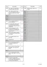
Jam Tray 2
-
In the case of printing by feeding
paper from the T2 paper tray unit,
after the T2 paper feed sensor
detects paper pass, the
registration front sensor does not
detect paper pass after a set
period of time.
Limit
Exceeded
Cancel printing.
The maximum number of pages
that can be printed is exceeded.
---
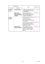
Error Message
State
Error
Codes
Refer
to:
Upper line
Middle line


