


V
- 3
- - - - - - - - - - - - - - - - - - - - - - - - - -
IMPORTANT
- - - - - - - - - - - - - - - - - - - - - - - - - - - - - - - -
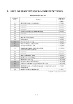
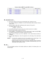
Basically, the maintenance-mode functions listed on the previous page should be accessed by
service personnel only. However, you may allow end users to access some of these under the
guidance of service personnel (e.g., by telephone).
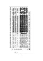
The user-accessible functions (codes 10, 11, 12, 82, 87 and 91) are shaded in the table given on
the previous page. Function code 10 accesses the firmware switches WSW01 to WSW41, each
of which has eight selectors. You should not allow end users to access all of those selectors, but
you may allow them to access user-accessible selectors which are shaded in the firmware switch
tables in Subsection 3.5.
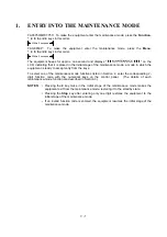
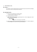
The service personnel should instruct end users to follow the procedure given below.
(1) FAX3750/MFC7750: Press the
Function
and
Mode
keys in this order.
FAX-8650P: Press the
Menu
and
Mode
keys in this order.
The LCD clears the current display.
NOTE:
The
Mode
key is inoperable during standby for redialing and timer.
(2) Press the
0
key.
(3) Enter the desired function code (10, 11, 12, 82, 87, or 91) with the numerical keys.
For function code 10, access the desired firmware switch according to the operating
procedure described in Subsection 3.5.
(4) To make the equipment return to the standby state, press the
Stop
key.
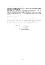
Function/Menu key
Mode key
0 key
Stop key
Содержание FAX-8650P
Страница 1: ...FACSIMILE EQUIPMENT SERVICE MANUAL MODEL FAX3750 FAX 8650P MFC7750 ...
Страница 5: ...CHAPTER I GENERAL DESCRIPTION ...
Страница 12: ...CHAPTER II INSTALLATION ...
Страница 13: ...CONTENTS 1 INSTALLING THE UPDATE DATA TO THE FACSIMILE EQUIPMENT II 1 ...
Страница 16: ...CHAPTER III THEORY OF OPERATION ...
Страница 18: ...III 1 1 OVERVIEW Not provided on the FAX 8650P ...
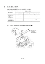
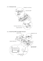
Страница 21: ...III 4 2 2 Laser Printing Mechanism 2 2 1 Paper pulling in registration feeding and ejecting mechanism ...
Страница 28: ...III 11 Not provided on the FAX 8650P Location of Sensors and Actuators ...
Страница 31: ...III 14 Main PCB Modem PCB ...
Страница 36: ...CHAPTER IV DISASSEMBLY REASSEMBLY AND LUBRICATION ...
Страница 42: ...IV 4 n n Disassembly Order Flow ...
Страница 71: ...IV 33 1 Provided on the FAX 8650P 2 Not provided on the FAX 8650P ...
Страница 72: ...IV 34 Setting up the main PCB after replacement ...
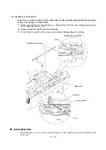
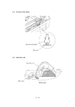
Страница 84: ...IV 46 2 Control panel locks 3 Scanner frame ASSY and separation roller gear ...
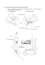
Страница 85: ...IV 47 4 Top cover lock spring 5 Gear drive unit ...
Страница 86: ...CHAPTER V MAINTENANCE MODE ...
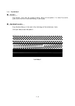
Страница 93: ...V 6 Scanning Compensation Data List ...
Страница 141: ...V 54 FAX3750 FAX 8650P MFC7750 Key Button Entry Order ...
Страница 146: ...CHAPTER VI ERROR INDICATION AND TROUBLESHOOTING ...
Страница 171: ...Oct 98 SM5X5303 Printed in Japan ...
Страница 172: ...FAX3750 FAX 8650P MFC7750 Appendix 1 EEPROM Customizing Codes ...
Страница 194: ......
Страница 195: ......
Страница 196: ......


