


VI
- 16
2.4
Troubleshooting Procedures
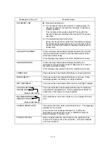
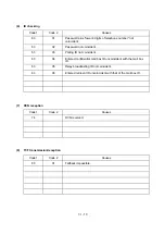
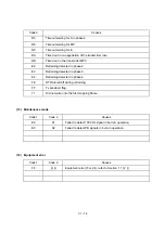
[ 1 ] Control panel related
Trouble
Check:
(1) LCD shows nothing.
l
Panel-main harness between the main PCB and the
control panel PCB
l
Control panel PCB
l
Low-voltage power supply PCB
l
Main PCB
l
LCD
(2) Control panel inoperative.
l
Panel-main harness between the main PCB and the
control panel PCB
l
Control panel PCB
l
FPC key
l
Main PCB
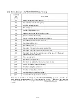
[ 2 ] Telephone related
Trouble
Check:
(1) No phone call can be made.
l
FPC key
l
Control panel PCB
l
NCU PCB
l
Main PCB
(2) Speed dialing or one-touch
dialing will not work.
l
Ordinary dialing function (other than the speed and
one-touch dialing)
If it works normally, check the main PCB; if not, refer
to item (1) above.
(3) Speaker silent during on-hook
dialing.
l
Ordinary dialing function (other than the on-hook
dialing with the hook key)
If it works normally, proceed to the following checks; if
not, refer to item (1) above.
(4) Dial does not switch between
tone and pulse.
l
Main PCB
(5) Telephone does not ring.
l
Speaker
l
NCU PCB
l
Main PCB
Содержание FAX-8650P
Страница 1: ...FACSIMILE EQUIPMENT SERVICE MANUAL MODEL FAX3750 FAX 8650P MFC7750 ...
Страница 5: ...CHAPTER I GENERAL DESCRIPTION ...
Страница 12: ...CHAPTER II INSTALLATION ...
Страница 13: ...CONTENTS 1 INSTALLING THE UPDATE DATA TO THE FACSIMILE EQUIPMENT II 1 ...
Страница 16: ...CHAPTER III THEORY OF OPERATION ...
Страница 18: ...III 1 1 OVERVIEW Not provided on the FAX 8650P ...
Страница 21: ...III 4 2 2 Laser Printing Mechanism 2 2 1 Paper pulling in registration feeding and ejecting mechanism ...
Страница 28: ...III 11 Not provided on the FAX 8650P Location of Sensors and Actuators ...
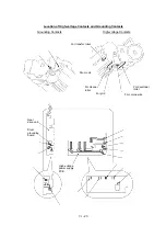
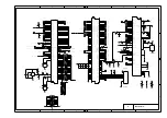
Страница 31: ...III 14 Main PCB Modem PCB ...
Страница 36: ...CHAPTER IV DISASSEMBLY REASSEMBLY AND LUBRICATION ...
Страница 42: ...IV 4 n n Disassembly Order Flow ...
Страница 71: ...IV 33 1 Provided on the FAX 8650P 2 Not provided on the FAX 8650P ...
Страница 72: ...IV 34 Setting up the main PCB after replacement ...
Страница 84: ...IV 46 2 Control panel locks 3 Scanner frame ASSY and separation roller gear ...
Страница 85: ...IV 47 4 Top cover lock spring 5 Gear drive unit ...
Страница 86: ...CHAPTER V MAINTENANCE MODE ...
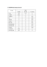
Страница 93: ...V 6 Scanning Compensation Data List ...
Страница 141: ...V 54 FAX3750 FAX 8650P MFC7750 Key Button Entry Order ...
Страница 146: ...CHAPTER VI ERROR INDICATION AND TROUBLESHOOTING ...
Страница 171: ...Oct 98 SM5X5303 Printed in Japan ...
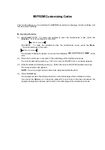
Страница 172: ...FAX3750 FAX 8650P MFC7750 Appendix 1 EEPROM Customizing Codes ...
Страница 194: ......
Страница 195: ......
Страница 196: ......


